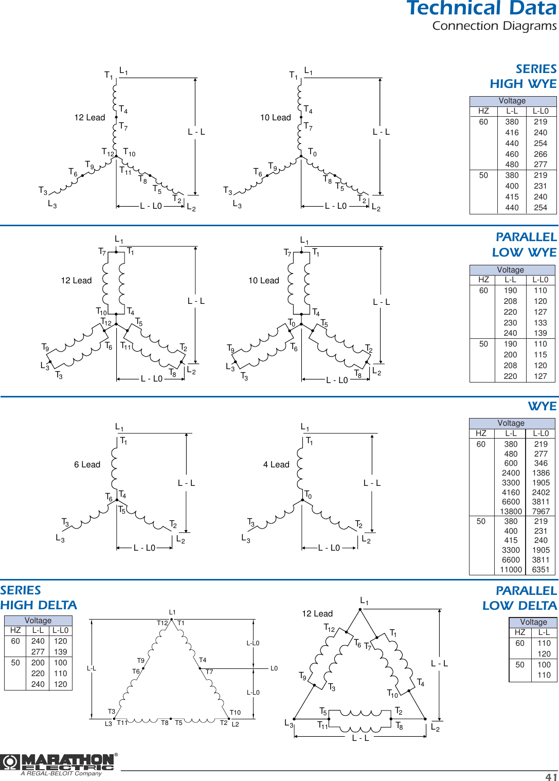
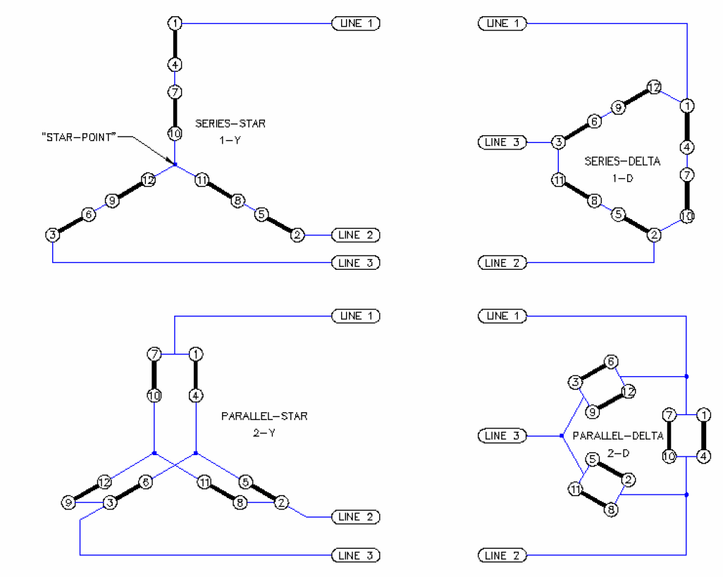
It should be some small number. 12 lead technical data connection diagrams series high wye parallel low wye wye series high delta voltage hz l l l l0 60 190 110 208 120 220 127 230 133 240 139 50 190 110 200 115 208 120 220 127.

12 Lead Generator Wiring Diagram Wiring Diagrams
12 lead generator connection diagram. It should be some small number. Then check from t4 t16. 12 lead generator procedure reference connection diagram 14002 31. 12 lead 11 8 t 9 t 12 t 7 t 10 l l0 l l l l0 l l l0 j single phase kwkva ratings are approximately equal to 50 of the generators three phase ratings. Check resistance from t13 t4. Compound generator all connections are for counterclockwise rotation facing the end opposite the drive.
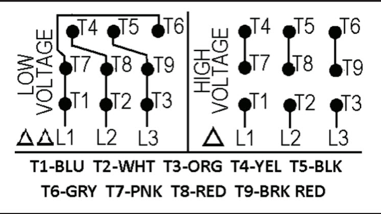
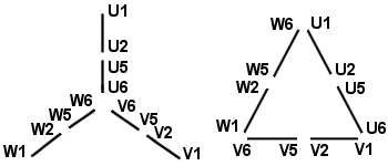
3 lead y 3 lead delta 6 lead y 6 lead delta 9 lead high voltage y 9 lead low voltage y 9 lead high voltage delta 9 lead low voltage delta 12 lead high voltage y 12. It should be a little bit smaller or about the same if not easily detectable. L1 l2 l3 join high wye 1 2 3 475869 101112. 10 and 12 lead low wye available voltages iso standard 10 lead generators are identical to 12 lead generators with the exception that u6 v6 and w6 are permanently bonded together as n 240v connections shown in blue 208v connections shown in red u n v u5 u2 v v w u6 u1 v1 v2 v5 v6 w1 w2 w6 w5 240v 208v. If t16 t4 is almost zero swap the lead numbers from t13 and t16. Collection of 3 phase motor wiring diagram 12 leads.
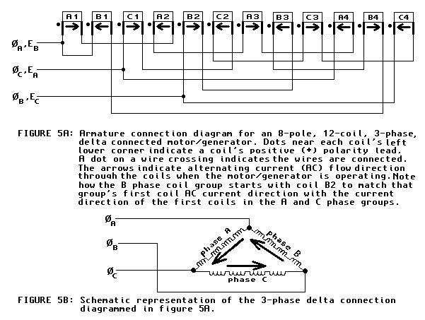
101112 dual voltage external wye connection voltage conn. In order to supply you with the correct generator end our staff will need you to supply the following information. This should be almost zero. The connections to the switch must be made so. Delta voltage hz l l 60 2402 7967 50 1905 6351 double delta single phase connection j voltage hz l l l l0 60 200 100 220 110 240120 50 220 110 parallel low zigzag single phase. A wiring diagram is a simplified traditional pictorial depiction of an electrical circuit.
Equal to 50 of the generators three phase ratings. Then check from t4 t16. It reveals the components of the circuit as simplified shapes and the power as well as signal connections between the gadgets. 12 lead generator procedure reference connection diagram 14002 31. It should be a little bit smaller or about the same if not easily detectable. For clockwise rotation interchange a1 and.
12 lead generator connection diagram 51 kb magnaplus dimensions 51 kb sae engine adapter and flywheel coupler measurement guide 162 kb generator sizing information. Check resistance from t13t4. If t16 t4 is almost zero swap the lead numbers from t13 and t16. This should be almost zero.


