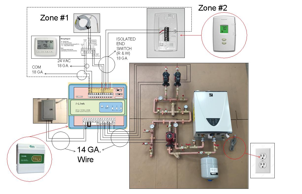
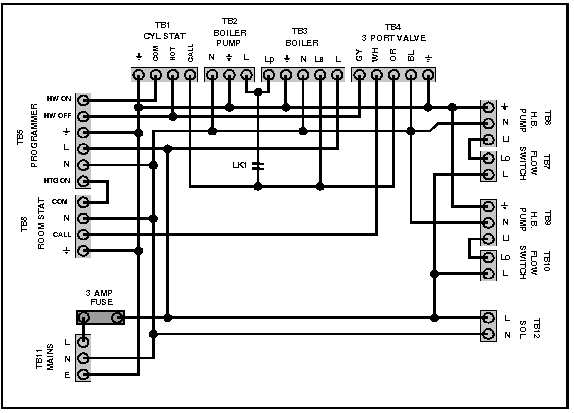
This is fine if the boiler is 120 v. When using alternative wiring diagram the boiler oper ating controls zc terminal will see the load of the circulators.

14i14t Diagram Schematic Boiler Control Panel Wiring Diagram
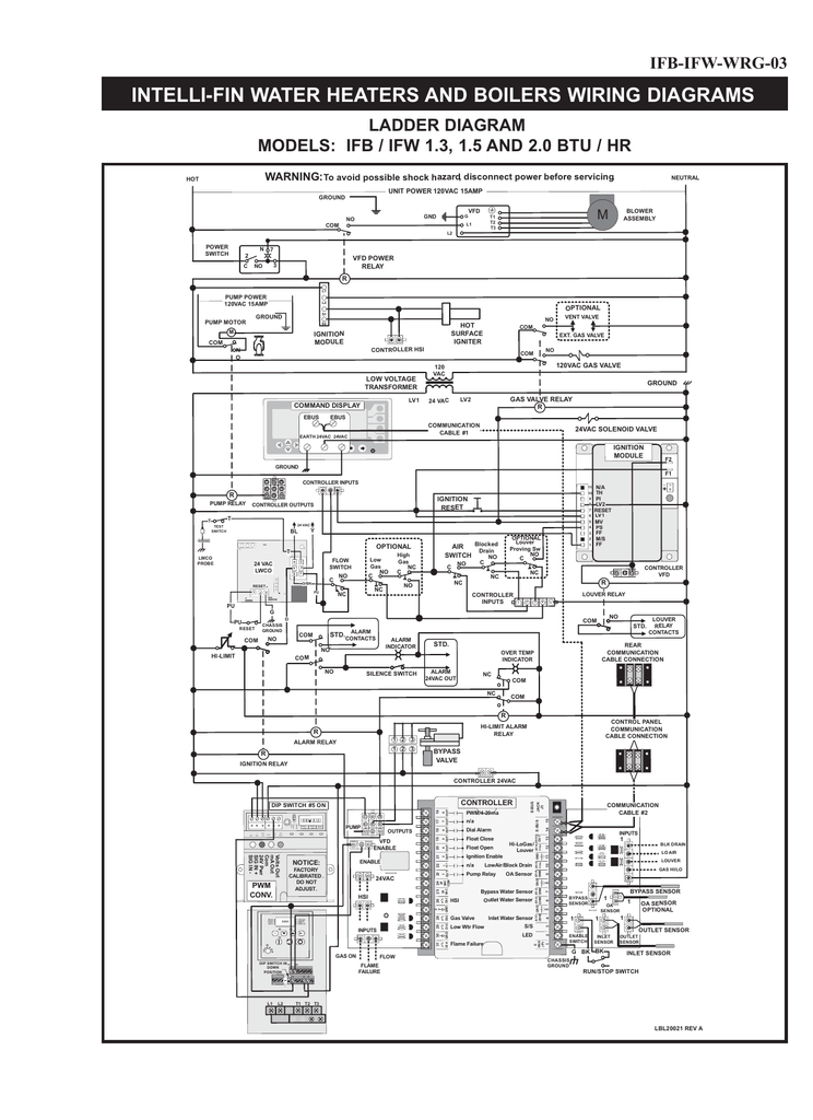
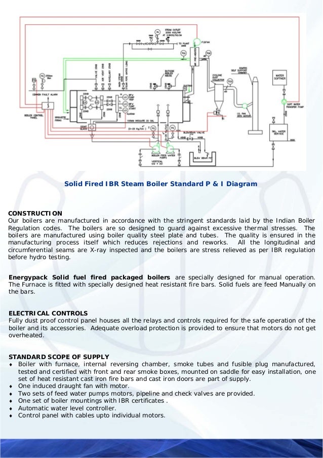
Boiler control panel wiring diagram. When using alternative wiring diagram wiring instructions must be followed so power originates from the boiler aquastat. See figure 4 page 20 this wiring diagram shows 120 v coming from l1 of a circuit breaker through a switch powering a boiler control and returning through l2 back to the neutral bar of the circuit breaker box. Steam boiler wiring diagram best boiler control panel wiring a novice s guide to circuit diagrams. The objective is the same. The diagram above is showing the boiler parts which are mandatory for the design and operation of steam boiler. Failure to follow these wiring instructions may result in a secondary source of power.
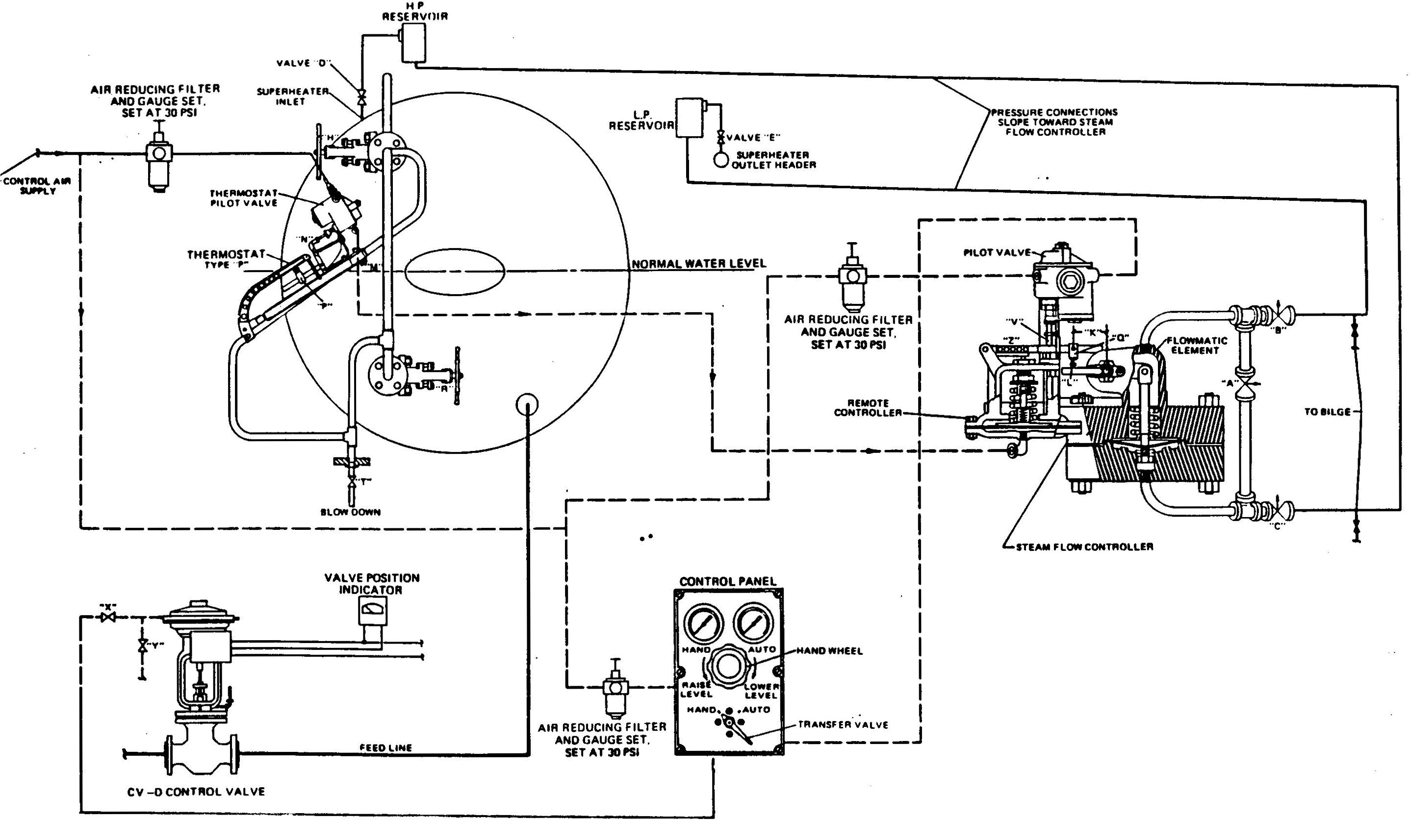
Hence each boiler part plays important role and everyone interested to know more about boilers can learn from this page in the last section. It shows how a electrical wires are interconnected and will also show where fixtures and components may be connected. Central boiler thermostat wiring diagram what is a wiring diagram. Boiler feed units with discharge piping electrical specifications. A first look at a circuit layout may be complex yet if you can check out a subway map you can check out schematics. Lets first see some basic information about boilers.
Float controls for manual and ac starters or customer supplied control panel condensate pump float switch wiring diagram pdf 343 kb condensate pump class 9038 mechanical alternator wiring diagram pdf 399 kb for boiler feed units. Getting from point a to aim b. Wiring the boiler the load is now a boiler. A wiring diagram is a straightforward visual representation in the physical connections and physical layout associated with an electrical system or circuit. Literally a circuit is the path that allows electrical energy to flow.


