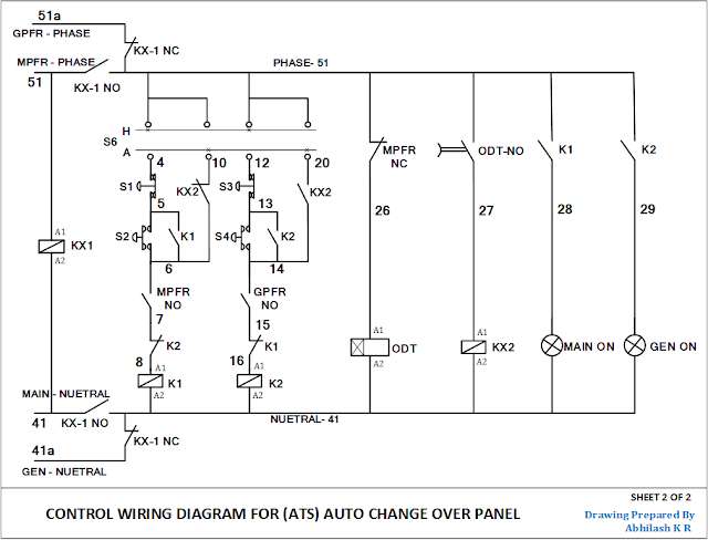
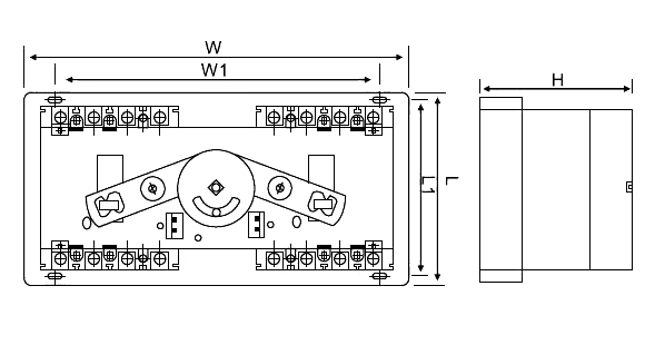
Automatic transfer switch with power distribution. Generac automatic transfer switch wiring diagram for exelent an.

Ctg And Ctgd Automatic Transfer Switch Ats Electrical
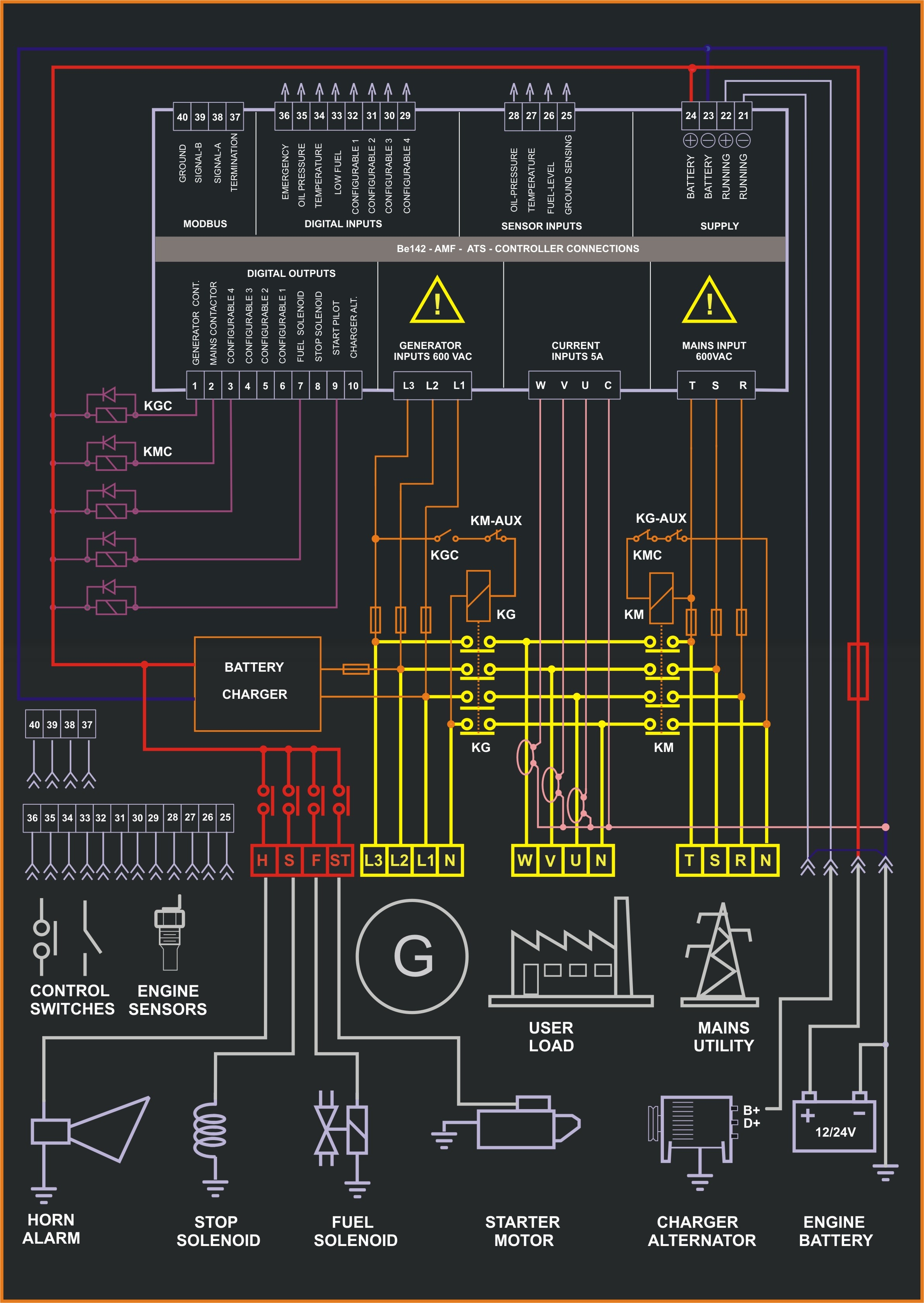
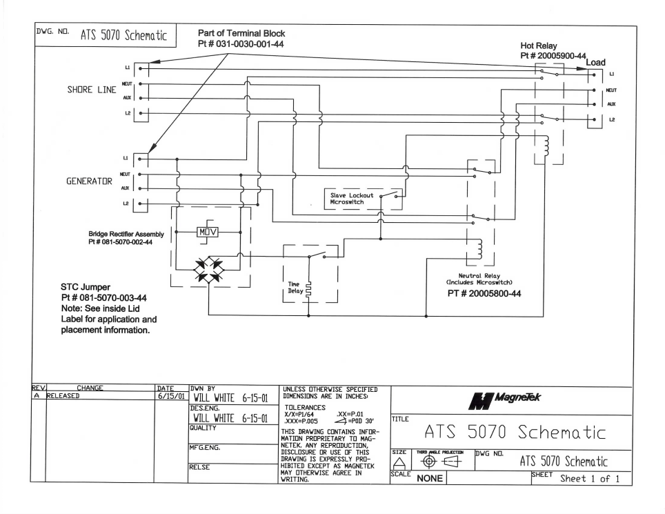
Ats panel circuit diagram. Breaker contactor or motorised switch socomec diagram. The bek3 controller is able to work from 5 up to 36vdc. An amf panel equipped with bek3 is designed to work with the power generator engine battery. Both circuit breakers are normally closed. On big jobs symbols might be numbered to show for instance the panel board and circuit to which the tool links and also to recognize which of numerous types of fixture are to be mounted at that area. The controller will guarantee remote control monitoring and functionalities when utility power is outside limits.
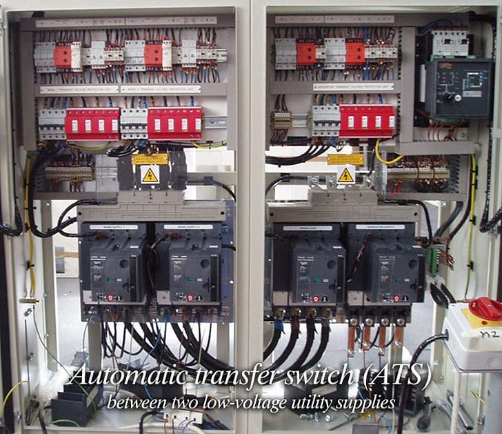
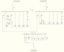
Using the bernini design generator controllers you can expand the visibility of you power system performance to your customers whether in the facility or off site through a on site server via the intranet or internet via gsm or via rs485 cable. In this video you will find out how to use phase failure relay in simple auto changeover application. Figure 1 shows automatic transfer between two low voltage utility suppliesutility source 1 is the normal power line and utility source 2 is a separate utility supply providing emergency power. Ats panel wiring diagram an automatic transfer switch wiring diagram an automatic transfer switch wiring diagram an generators 120 vac 50 amp automatic transfer switch from progressive dynamics generator transfer switch. The load must be able to tolerate the few cycles of interruption while the automatic transfer device operates. A distribution board also known as panelboard breaker panel or electric panel is a component of an electricity supply system that divides an electrical power feed into subsidiary circuits while providing a protective fuse or circuit breaker for each circuit in a common enclosure.
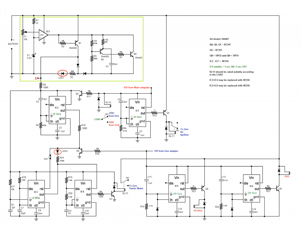
Updated ats circuit diagram with complete ic 4060 and ic 555 wiring details. The idea of the system is simple. Technical information 3 standard diagrams transfer between 2 sources 1 bus bar. Designed and written by. Amf control panel circuit diagram pdf description. When there is a power failure on mains 1 the pfr will open.
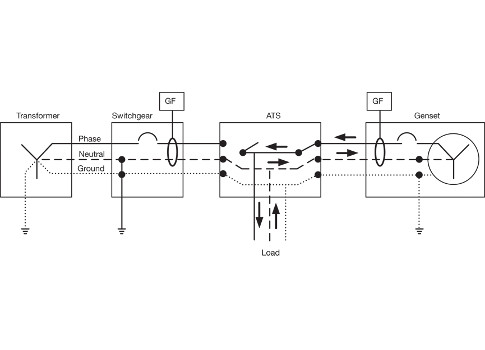
12 selection the size of automatic transfer switch 13 automatic transfer switch components 14 modes of operation 15 schematic circuit diagram for automatic transfer switch 16 recommended cable size 17 specifications 171 general specification 172 controller specification 18 ordering information 19 detailed drawings. Motorised switch cl ncl g q1 q2 ats automatic transfer switch protection arent shown on the following schemes summary. The atsgtsups end system must be correctly grounded for proper operation. The following article explains an enhanced automatic transfer switch ats circuit which includes several customized sequential changeover relay stages making the system truly smart.
