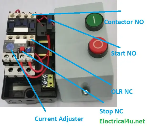
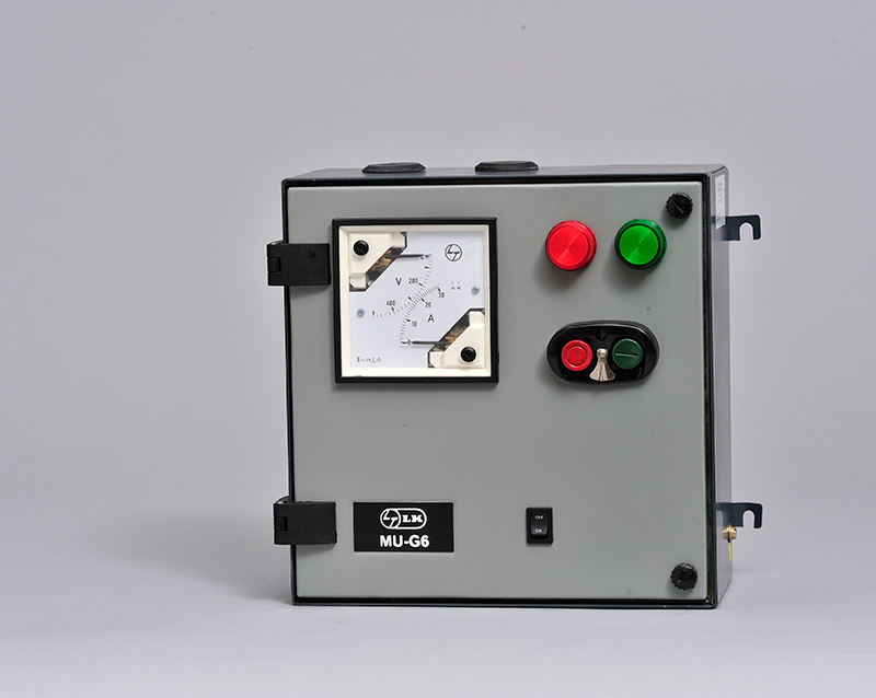
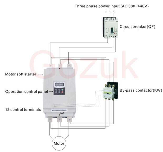
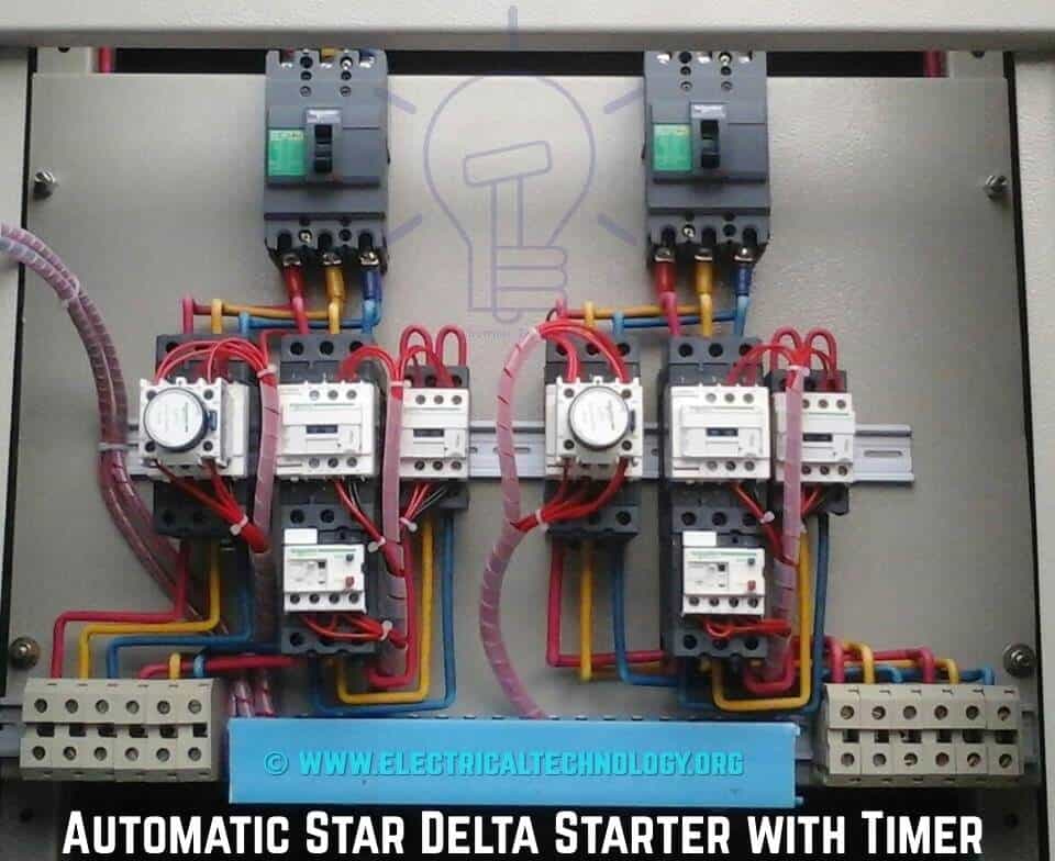
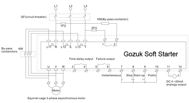
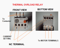
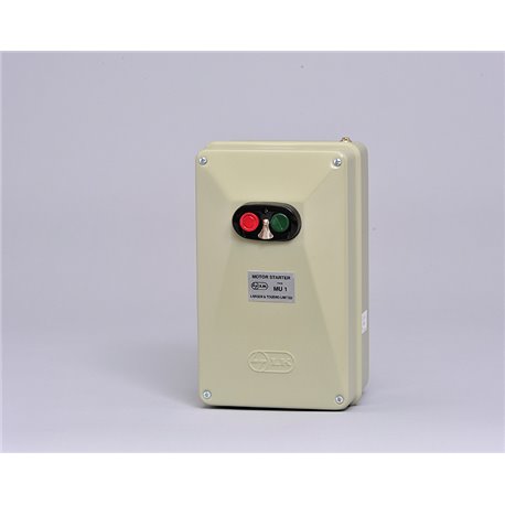
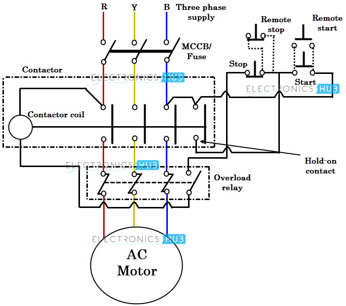
In this post we are going to know the details of each part of dol starter diagramall parts of the dol starter power circuit diagram and control circuit diagram are explaineddirect online starter or dol starter is very useful and commonly used ac starterdol starters are mainly used with up to 5 hp motors. A dol starter or direct on line starter or across the line starter is a method of starting of a 3 phase induction motorin dol starter an induction motor is connected directly across its 3 phase supply and the dol starter applies the full line voltage to the motor terminals.
Crompton Dol Starter Wiring Diagram Diagram Base Website
L t dol starter control circuit diagram. The maximum size of a motor allowed on a direct on line starter may be limited by the supply utility for this reason. The power and control circuit will be wired in the same circuit. The dol starter is made of a circuit breaker or mccb or fuse an overload relay and contactor or coil. The wiring of direct on line control circuit starter is following. The contactor is used for starting and stopping the motor where the green and red buttons are connected. Direct online starter circuit diagram.
The circuit breaker is used for protection against short circuits while the overload relay protects the motor from overloading. Generally two kinds of direct online starter wiring diagrams are implemented. In the above three phase dol starter wiring diagram. Their website does not have a data sheet or wiring diagram. If that motor starter is a dol. Here remote operation is not possible.
And one wiring is called controlling wiring. Despite this direct connection no harm is done to the motor. In the below dol starter wiring diagram i shown a molded case circuit breaker a magnetic contactor normally open push button normally close push button switch thermal overload relay motor trip indicator and 3 phase motor. Direct on line motor starter dol is suitable for. A direct on line starter can be used if the high inrush current of the motor does not cause excessive voltage drop in the supply circuit. Dol starter control wiring diagram with timer pdf direct online starter connection diagram.
The connection of contactor can be done among relay coil supply voltage as well as thermal overload. Conventional dol starter has own startstop circuit. What is dol starter. The l1 contactor is connected from normally open no to r phase using mccb. One is a conventional type and another one is the industrial type. Type you should be able to mimic the are dol motors from lt.
Lt dol starter wiring diagram lt dol starter wiring dol starter connection in hindi. L t dol starter circuit diagram the starter will have wires labeled t1 t2 t3 l1 l2 l3 and two switch wires labeled s1 and s2 step 3 inspect the three phase power supply disconnect box. Lt dol starter wiring diagram repiring dolstater ltdolstarter dolstarterwiringdiagram electrical electricalknowledge. Dol starter control diagram three phase.
_2.png)
