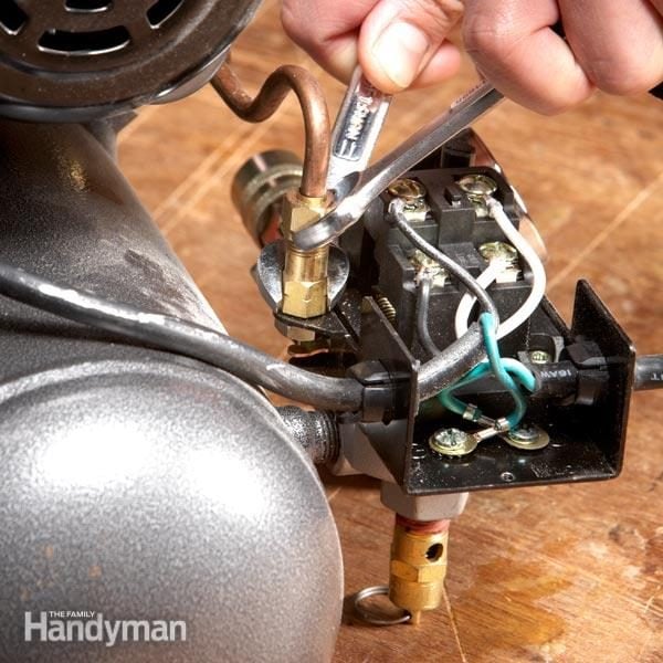
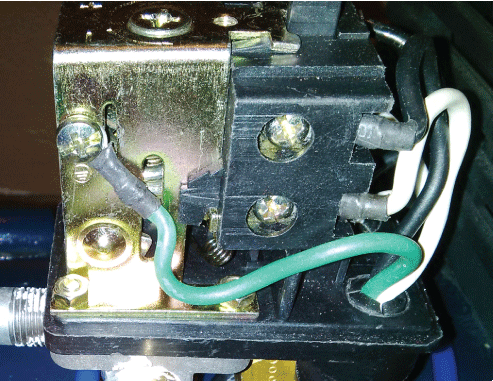
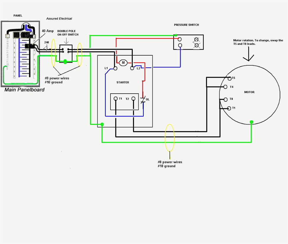
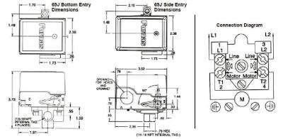
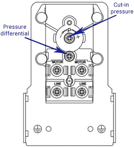
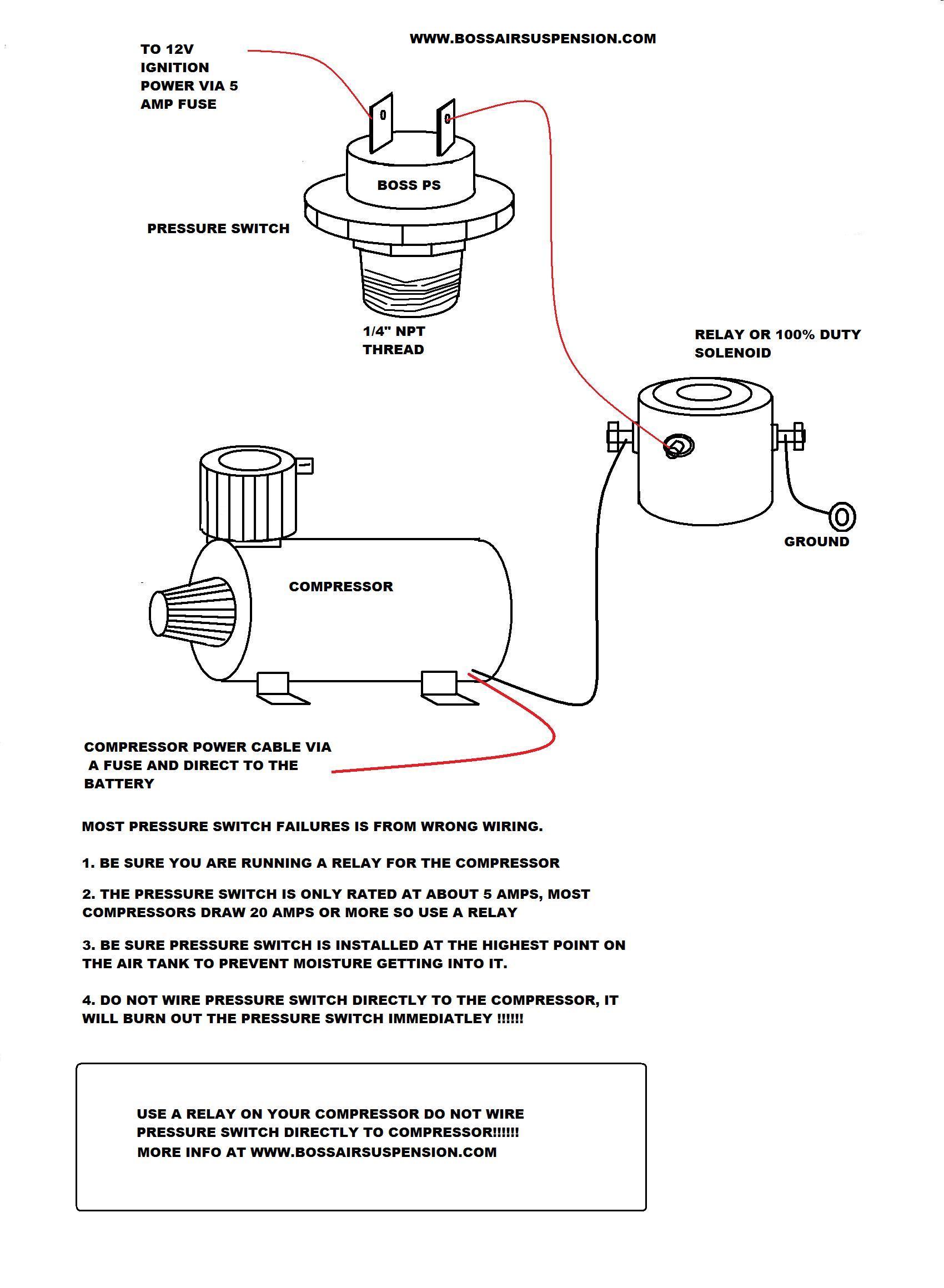
This will burn the compressor motor will cause extra wear on the compressor components and will damage the pressure switch. On an air compressor with a pressure switch always bring the incoming power to the line contacts of the pressure switch.
Arb Compressor Simplify The Wiring Jk Forum Com The Top
Air compressor pressure switch diagram. Do not wire directly to the motor as this will cause the motor to run. Variety of air compressor pressure switch wiring diagram. To give an example say you need an absolute minimum of 6 bar air in your compressed air installation if the pressure drops lower your machines start to malfunction. Air leaking under pressure switch air compressor check valves one way non return duration. A wiring diagram is a simplified traditional pictorial depiction of an electric circuit. Rotary screw compressors can be run at lower temperatures and for 24 hours a day 365 days a year.
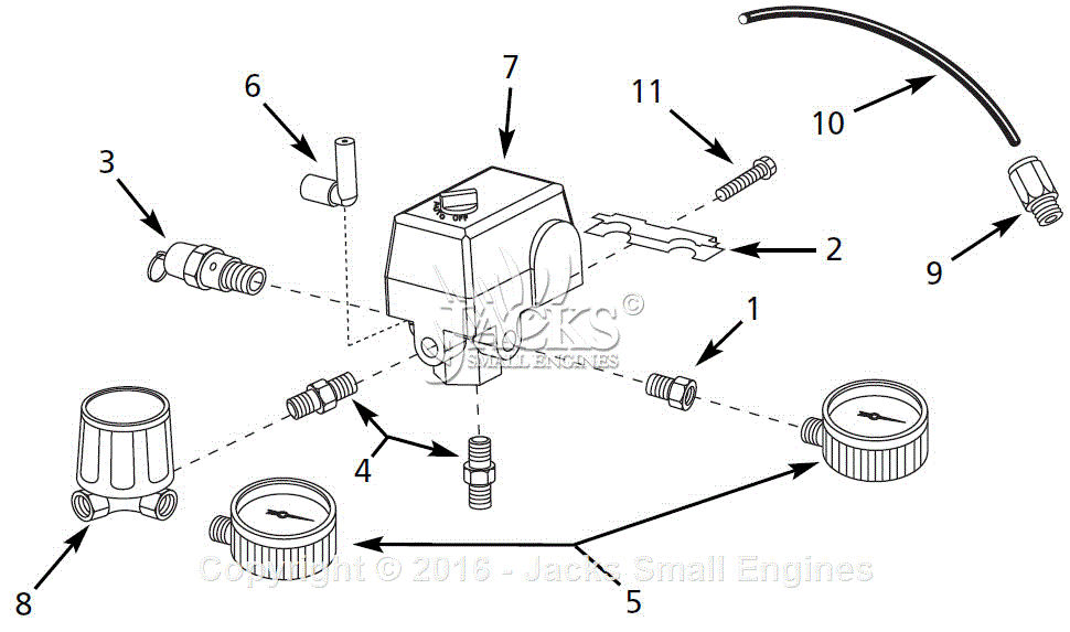
The fitting on the left is where the unloader valve line connects and the vertical nipple on the right is where the pressure switch is mounted on this small diy air compressor. Add to compare compare now. The switch may be wired correctly yet if a full path the motor allows the compressor to cut in when the pressure is low cut out when the pressure is at the stopping point the compressor stops and thats repeatable without the switch in the circuit and then when you add the switch there doesnt appear to be enough power to drive the. A wiring diagram is a simplified conventional photographic depiction of an electrical circuit. Fixed range screw arrangement for pressure switch. In the fixed range switch there will only be one screw for adjusting air compressor pressure switch.
Air compressor magnetic starter wiring duration. Sunny heavy duty 25 amp air compressor pressure switch control valve 145 175 psi. Collection of pressure switch wiring diagram air compressor. Gt air projects 83812 views. Lefoo quality air compressor pressure switch control 95 125 psi 4 port w unloader lf10 4h 1 npt14 95 125. It reveals the parts of the circuit as simplified forms as well as the power and also signal connections between the tools.
Air compressor pressure switch diagram. A rotary screw is a compressor which utilizes two intermeshing helical rotors to trap a volume of air then compress it to a higher pressure. The copper line sitting on the tank is the unloader line which connects from the tank fitting tank check valve on the left over to the unloader valve on the pressure. It shows the components of the circuit as streamlined shapes as well as the power and also signal links between the devices. Here is a little brief on the fixed range and adjustable range screw arrangements for compressor switches.
