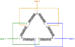
1 ohm meter 2 6 or 12 volt battery 3 tape to label leads 4 copy of augie. Steve discusses how to identify unmarked 9 lead delta connection on a motor.

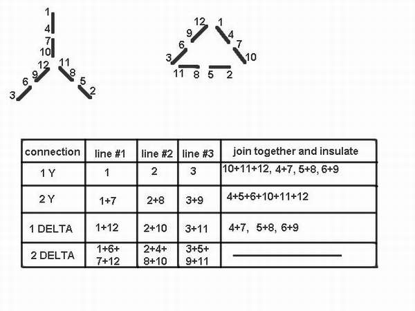
12 Leads Terminal Wiring Guide For Dual Voltage Delta
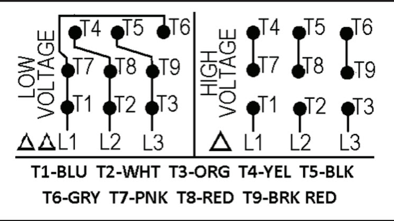
9 lead motor connection diagram. In such case each cable will be marked with the appropriate lead number. Each lead may have one or more cables comprising that lead. Three phase see below single voltage. 3 lead y 3 lead delta 6 lead y 6 lead delta 9 lead high voltage y 9 lead low voltage y 9 lead high voltage delta 9 lead low voltage delta 12 lead high voltage y 12. For specific leeson motor connections go to their website and input the leeson catalog in the review box you will find connection data dimensions name plate data etc. 3 phase motor wiring diagram 9 leads perfect luxury 9 lead motor.
Single phase dual voltage 11 lead thermally protected cw rotation. 3 phase motor wiring diagram 9 leads collections of amazing baldor electric motor wiring diagram motors 10 3 wiring. Motor wiring diagram 9 lead dual voltage wye connection part winding start pws on low voltage to reverse direction of rotation interchange leads l1 l2. Single phase single voltage 3 lead cw or ccw rotation. 12 lead dual voltage y d or 6 lead single voltage y d. Always use wiring diagram supplied on motor nameplate.
All 9 leads motors are most commonly made for dual voltage application this means that the motor was manufactured specifically for dual voltage operation which can be connected in either. Delta connection we will need. Single phase 115230v 7 lead w thermal protection cw rotation. Wye connection dual voltage with thermal protector. Electric motor wire marking connections. It is of utmost importance to firstly understand the internal wiring configuration of a 9 leads ac induction motor before doing the actual wiring connection.
Dayton electric motors wiring diagram gallery. 3 phase wire diagram daytonva150.


