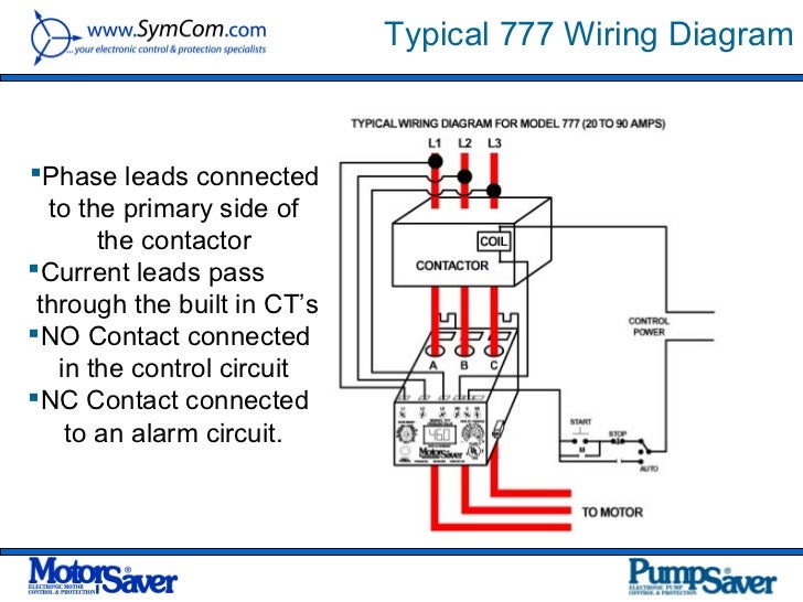
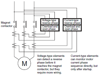
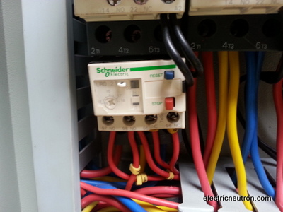
The overload relay is designed so the current to the motor is shared between phases so if you only wire up one phase then all the motor current goes through one of the contacts on the overload and you can. Its is important to.

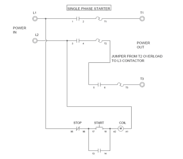
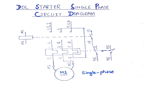
Figure F 1 Wiring Diagram Single Phase
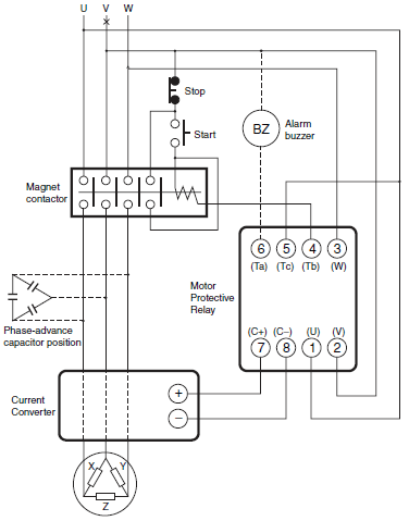
Single phase overload relay wiring diagram. Previously we discussed what a magnetic motor starter is a contactor and an overload relay. Zoeller and grinder pumps can be retrofitted to ex. Thermal overload relay wiring diagram awesome 3 phase electric motor. Motor winding resistance values. Easy and simple wiring diagram to make you learn easily watch the video and subscribe my youtube channel. The start and stop circuits could alternatively be controlled using a plc.
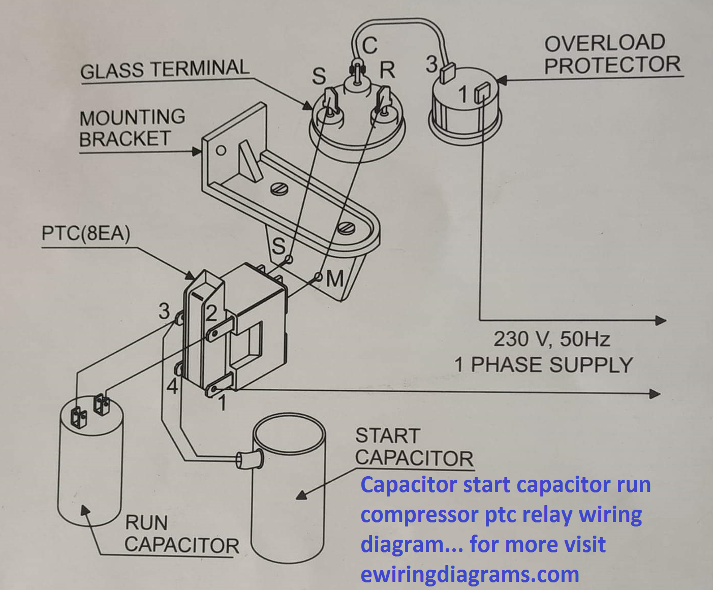
An accurate panel wiring diagram. Siemens overload relay wiring diagram sample. This diagram is for single phase motor control. Relay start capacitor 1 2 5 to motor blk red red org yel 3 1 surge arrestor main overload 1 2 blk yel blk red blu blk yel blk org blk run capacitor start capacitor ground lead ground lead l1 l2 yel blk red start. Contactor wiring and i hope after this post you will be able to wire a 3 phase motor i also published a post about 3 phase motor wiring with magnetic contactor and thermal overload relay but today post and contactor wiring diagram is too simple and easy to learn. Thermal overload relay wiring diagram gallery collections of wiring diagram for motor starter valid wiring diagram direct line.
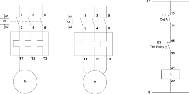
Dol starter control and power wiring by using a fuse contactor overload relay motor. Contactor wiring guide for 3 phase motor with circuit breaker. It uses a contactor an overload relay one auxiliary contact block a normally open start pushbutton a normally closed stop pushbutton and a power supply with a fuse. As a result of this if a single phase supply is wired such that line and neutral pass through just 2 of the 3 elements the overload can trip. This manual is intended to assist in the installation. As a result of this if a single phase supply is wired such that line and neutral pass through just 2 of the 3 elements the overload can trip.
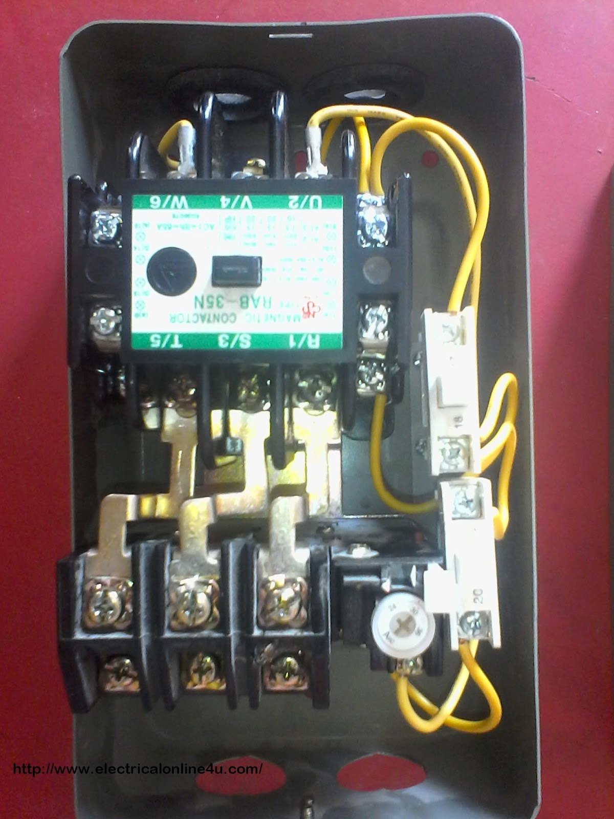
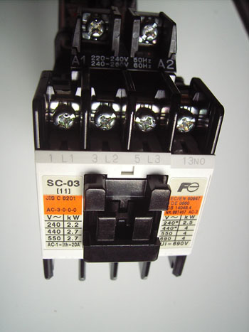
2 days ago i wired 380 to 440 volts contactor for a 3 phase motor and save these images of contactor in pc. To avoid this problem when using a standard overload with a single phase motor load the wiring through the overload must be arranged so that all three elements are in the circuit. A set of jumper wires. To avoid this problem when using a standard overload with a single phase motor load the wiring through the overload must be arranged so that all three elements are in the circuit. Pump performance and. Single phase motors controls start overload line power from two pole fused switch or circuit breaker and other control if used.
Voltage ohm and for single phase systems. Single phase motor overload protection. Single phase units have an internal thermal overload.

