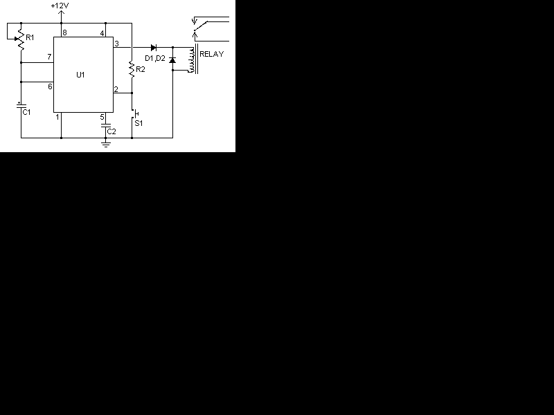
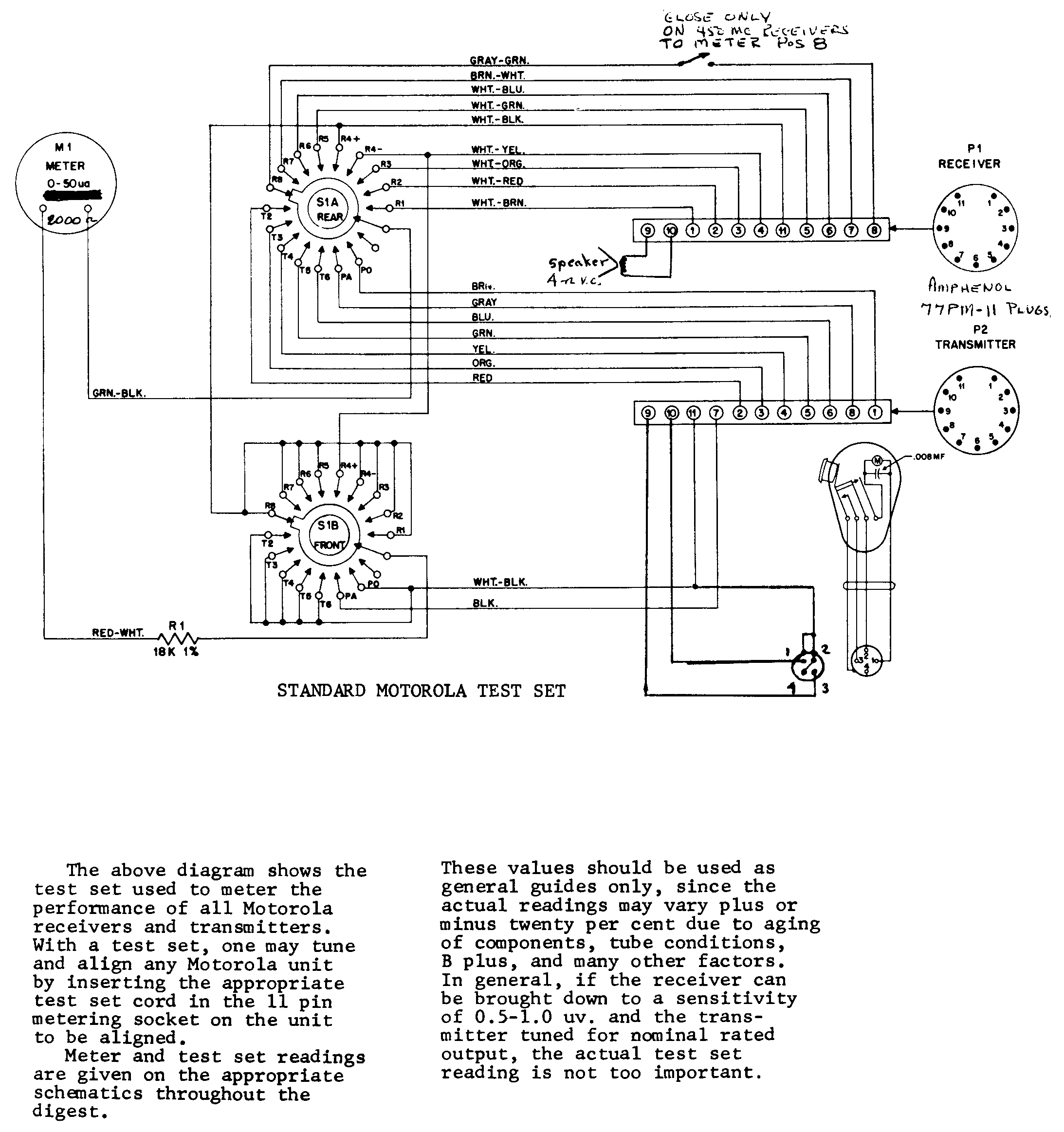
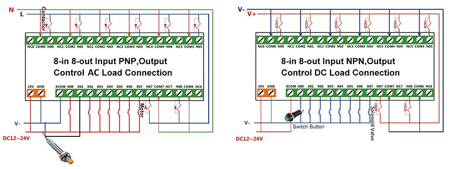
This guide even consists of ideas for added provides that you might require as a way to end your tasks. This post is about the staircase timer wiring diagram.
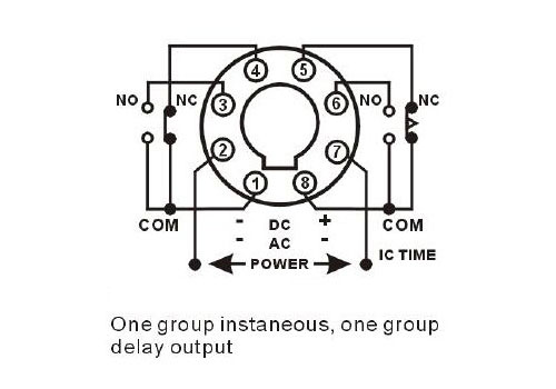
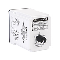
Digital Timer Relay 8 Pin 12v 24v 220v
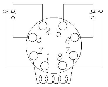
8 pin timer relay wiring diagram. It shows the components of the circuit as simplified shapes as well as the power and also signal connections in between the gadgets. 8 pin relay connection 8 pin relay wiring diagram. Assortment of 8 pin ice cube relay wiring diagram. A wiring diagram is a simplified standard pictorial representation of an electric circuit. Wiring diagram also offers helpful recommendations for projects that might require some extra tools. 8 pin relay wiring diagram.
Relay 8 pin wiring diagram datasheet cross reference circuit and application notes in pdf format. Mostly we use the 8 pin timer in ats system automatic transfer switch star delta starter and many other places where we needed the timing in circuit. These relay are connected in a socket which is also called base. This post is about the 8 pin timer wiring diagram. 8 pin relay wiring. Through the thousands of images on line regarding 8 pin relay wiring diagram choices the top collections having greatest image resolution exclusively for you and now this photos is usually one of pictures selections inside our ideal graphics gallery about 8 pin relay wiring diagrami hope you might enjoy it.
We have also more glass types of relay such as 14 pin relay and 11 pin relay. Please make sure that the motor is properly grounded to the system ground especially if the motor has a metal casing. This is the staircase wiring with timer i shown how to use relay with timer as reset and hold switch. 8 pin relay wiring. 8 pin relay wiring diagram symbol diagram. This post is about the 8 pin relay wiring diagram.
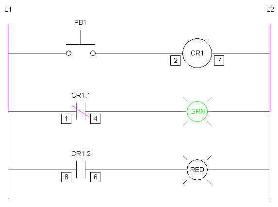
Pin 3 is connected to the motors power in side and pin 8 is connected to the motors neutral connection. The below diagram is on delay timer wiring diagram. A 8 pin is glass type relay which we mostly used for different types of controlling and switching circuits. Ladder and wiring diagram using an 8 pin electrical relay to turn on and off lights. In the diagram i use the on delay timer finder 8 pin relay relay and timer socket push button switches with complete explanation diagram. This photograph how to wire a relay in 8 pin relay wiring diagram earlier.
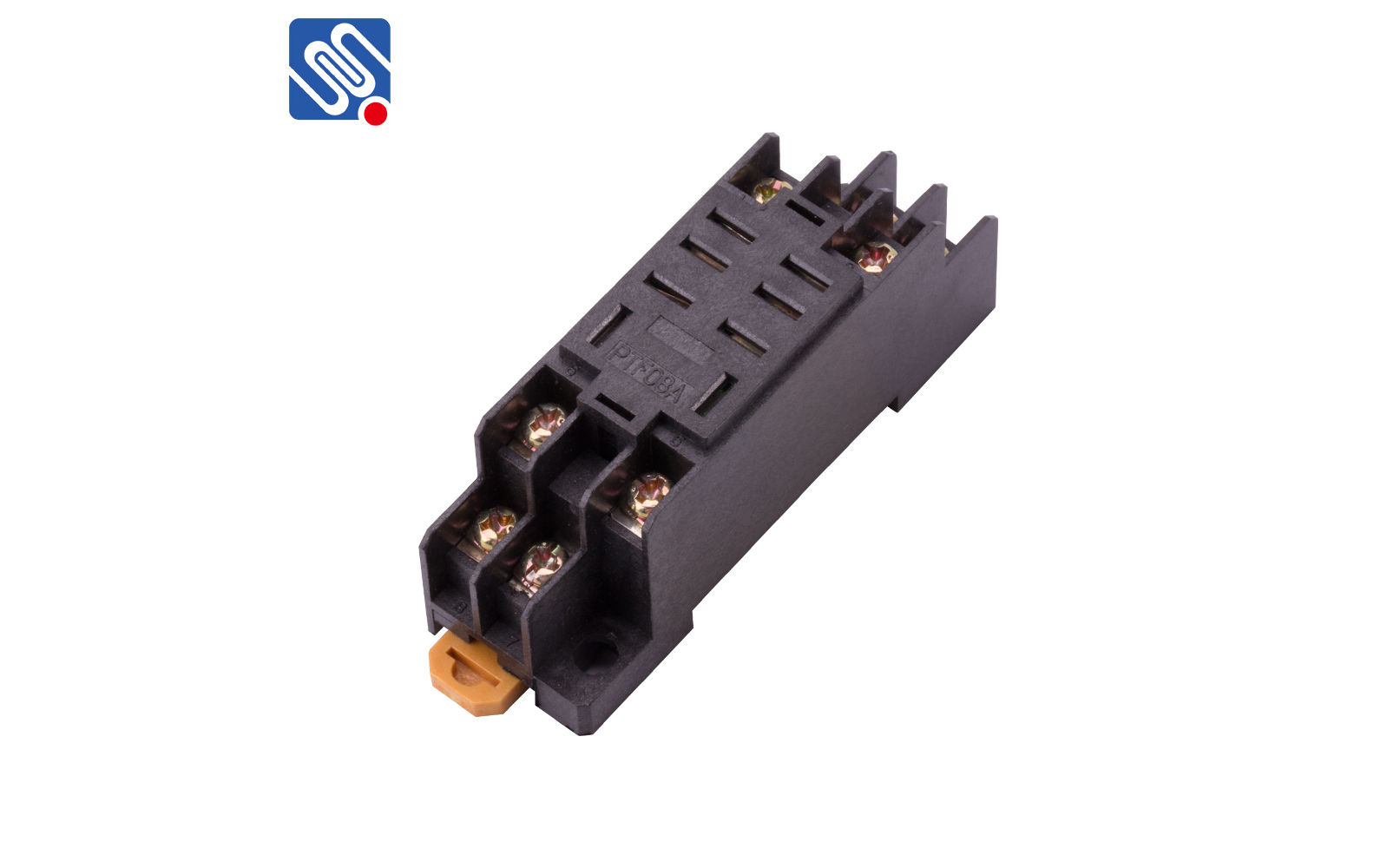
When the photo switch output becomes active it will supply the relay coil pin 2 with 110vac and the relay will become. These relay are connected in a socket which is also called base. Note that to wire a 8 pin timer we use the 8 pin relay socket. Pins 8 6 as normally open pins 8 5 as normally closed.


