Terminals 3 and 4 represent the toggle switch. Buy these onoff switches from oznium.

Awesome Push Button Ignition 5 Steps With Pictures
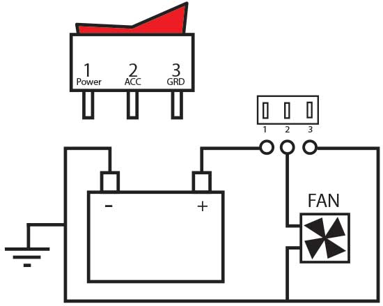
3 pin momentary switch wiring diagram. Navigation and anchor light rocker switch wiring guide duration. Switches with two pilot lights. With independent lamp circuit only 3. 6 pin toggle switch wiring diagram collection 3 prong toggle switch diagram beautiful rocker switch wiring. 3 position toggle switch wiring diagram elegant switches can a. This rocker is perfect for an engine offrunstart switch.
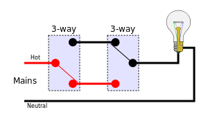
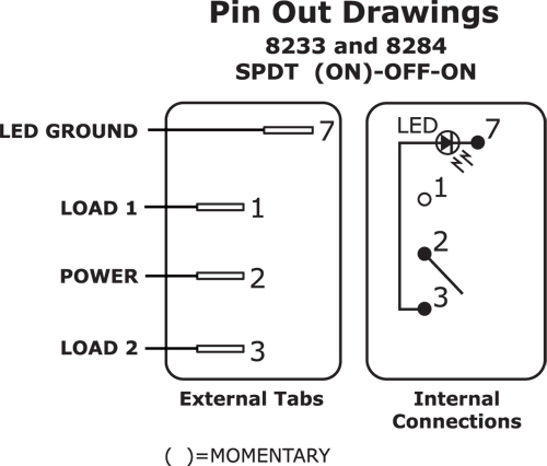
9 pin toggle switch wiring diagram 6 pin rocker switch wiring. Rocker switch wiring diagram. Nov 4 attachment i have a 7 pin on off on rocker switch that i am trying to wire up i have a diagram that i have attached that came with it and awaterwich 7 pin momentary winch in out rocker toggle switch waterproof dc 20a 12v10a 24v black shellon off on dpdt illuminated rocker switch for auto truck boat marine off road winch. 3 pin rocker switch wiring diagram. Carling toggle switch wiring diagram. The type of control you perform every time you walk into a dark room.
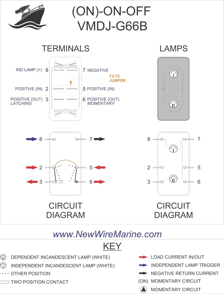
The wiring diagram below will demonstrate how to to wire and power this 12v 20amp on on off 3 way carling contura rocker switch. These terminals receive the power necessary to drive the loads on terminals 1 and 5 and 2 and 6. In this video we are giving a tutorial on how to wire a rocker switch with led 6 and 7 pin wiring diagrams to control a linear actuator as well as showing how exactly a rocker switch works. It is off at the bottom on in the center and momentary on at the top. This is a rocker switch body only. It is off at the bottom on in the center and momentary on at the top.
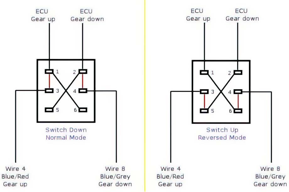
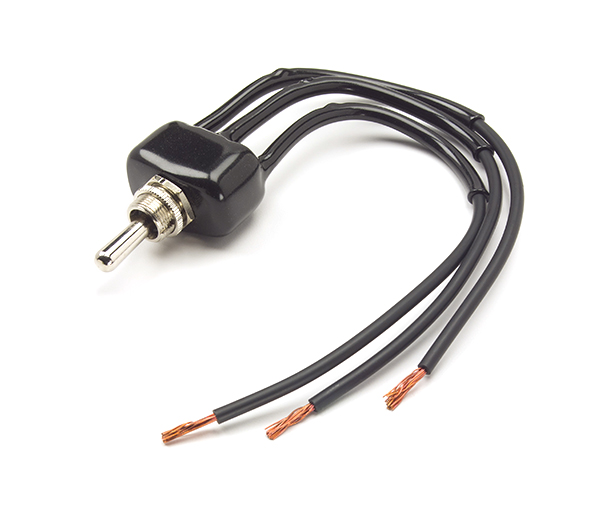
How to wire a dual led rocker switch 5 pin duration. Usually the onoff switch will be maintained like a toggle or slide switch but momentary onoff switches can have their purpose. We will now go over the wiring diagram of a dpdt toggle switch. A dpdt toggle switch has 6 terminals. To convert connect jumper wire from terminal 3 to terminal 6 and connect terminal 4 to ground diagram f diagram g1 diagram g2 b l 2 4 3 b l 2 4 36 b l 2 4 36 jumper single pole sp double pole dp switch wiring diagrams diagrams represent both momentary contact or maintained contact switches. Below is the schematic diagram of the wiring for connecting a dpdt toggle switch.
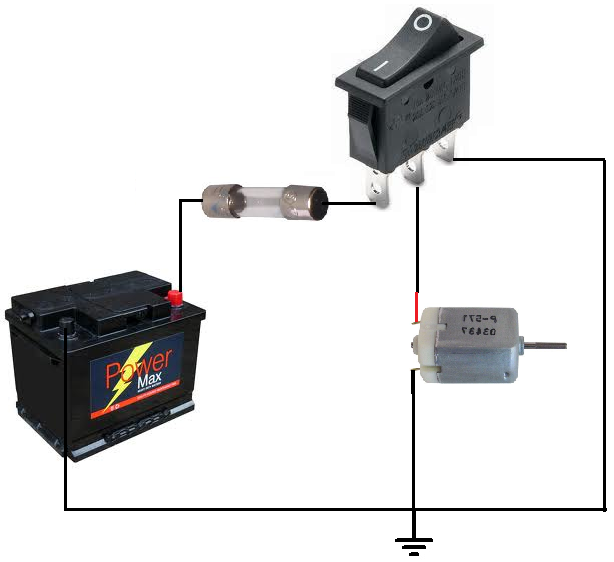
The vmdj is a unique dpdt momentary rocker switch. Rocky x tv 227699 views. An onoff switch can be implemented by simply sticking an spst switch in series with a power line. With lighting sequences 10 20 30 4050 only.

