Three phase systems are extremely common in industrial and commercial settings. You may also read.

Induction Motor Braking Regenerative Plugging Dynamic Braking
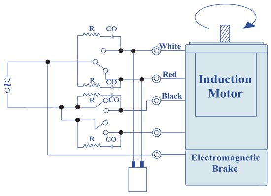
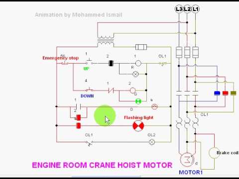
3 phase brake motor wiring diagram. One line diagram of simple contactor circuit. Electric motor brake wiring diagram collections of wiring diagram dual light switch 2019 2 lights 2 switches diagram. Multi speed 3 phase motor 3 speeds 1 direction power control diagrams. On request dc brake can be provided with a rectifier integrated in the. Baldor motor wiring diagram baldor 5hp motor wiring diagram baldor brake motor wiring diagram baldor dc motor wiring diagram every electrical structure is composed of various diverse parts. Three phase electrical wiring installation in home iec nec.
Which allow the motor brake system to cycle at a very high rate. Electric trailer jack wiring diagram download. 230yy460y volts 60 hz 200yy400y volts 50 hz. If not the arrangement will not function as it should be. Wiring diagram 6 lead 3 phase 480 volt motor wiring library 3 phase motor wiring diagram 6 wire wiring diagram contains the two examples 3 phase motor wiring diagram 12 leads june 15 2020 wiring diagram by anna r. W2 cj2 ui vi wi w2 cj2 ui vi wi a cow voltage y high voltage z t4 til t12 10 til t4 t5 ali l2 t12 ti blu t2 wht t3org t4 yel t5 blk t6 gry t7 pnk.
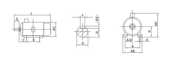
K bapk bak with k brake disc for hoisting applications the ba series consists of three phase asynchronous brake motors totally enclosed fan cooled tefc. How to connect a portable generator to home supply system three methods a simple circuit diagram of contactor with three phase motor. Although these systems may seem intimidating at first a walkthrough on 3 phase wiring for dummies will help clarify the whole situation. Electric motor brake wiring diagram image. Different regions may use different voltages. 3 phase wire diagram daytonva150.
Each component should be set and connected with different parts in particular way. They can also be found in large residential complexes and appliances requiring a large amount of power. The bmk brake control system optional for frame sizes 71 to 225. The final stage of brake installation onto the motor is mounting the fan and inserting the brake supply cable into the motor terminal box 8. The bme can we wired to operate for. Connection diagram dt79 example motor voltages.
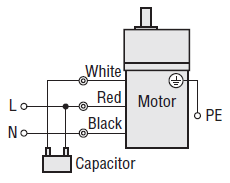
As standard the brake power supply is ac 3 phase. Connect the brake supply cable inserted into the motor terminal box according to the diagram on the inside of the box cover while connecting the brake with the motor maintain all the necessary. The ba series range starts from 71 up to 315 frame size. Capacitor motor single phase wiring diagrams always use wiring diagram supplied on motor nameplate.


