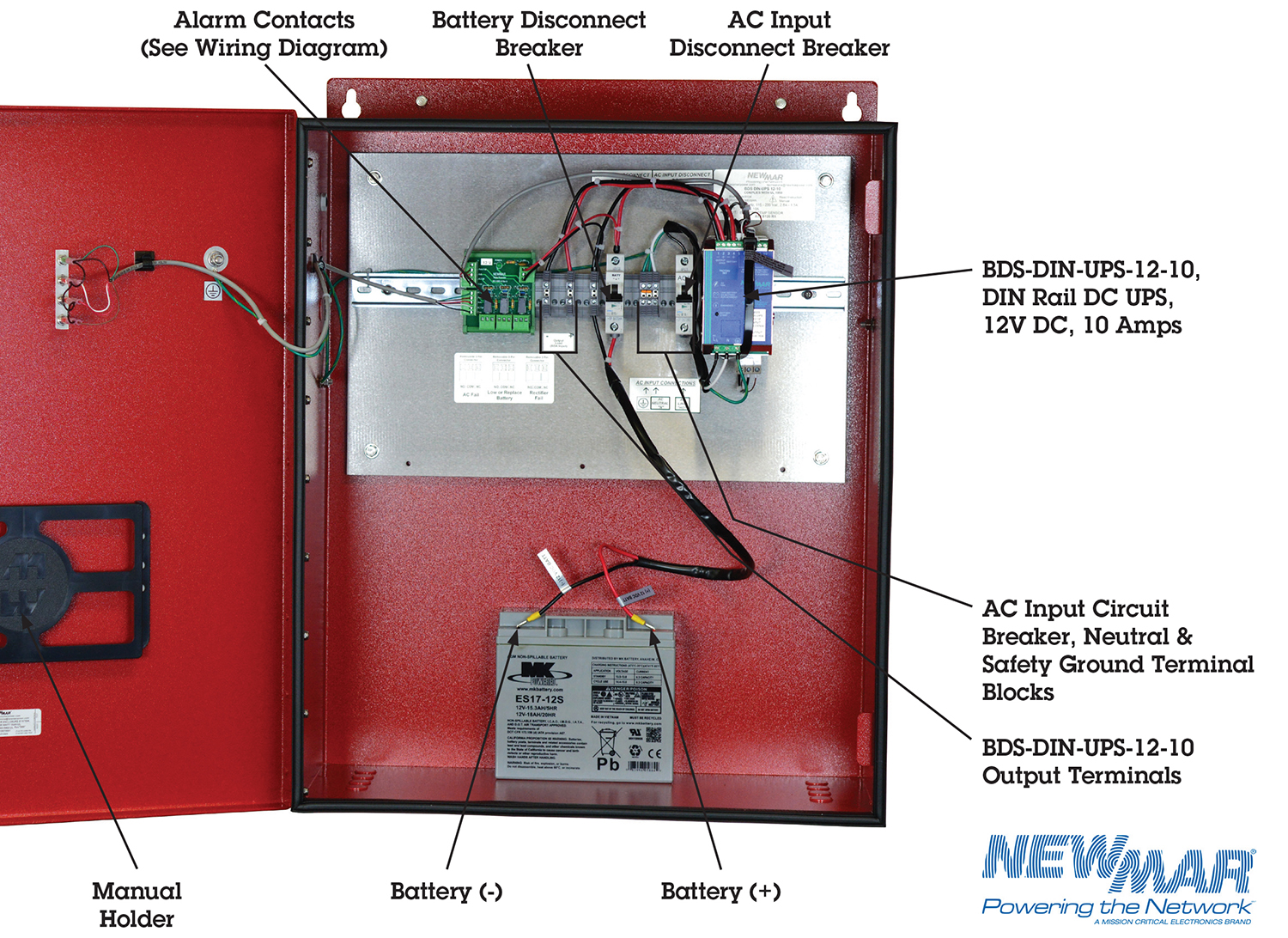
The model is 430 71013 and is from an apc ups and there are 2 of these that run in series each has a 4 wire connection on the main board and the terminals on the mainboard look to be in parallel. In today ups inverter installation tutorial we will show how to connect and install the battery backup power through.

Vt 2233 Phase Ups Pure Sine Wave Schematic Diagram Datasheet
Home ups wiring diagram datasheet. Based on the value entered we will estimate the run time that you will have during a total power outage. And this ups have two voltage correction two step up ou step down voltage options. 24 v dc10 a including mounted universal din rail adapter uta 10730. Adding run time increases availability by allowing the system to operate through longer outages without shutting down. I will try to find out some document about it with my old friends from apc i am an ex employ have worked for 8 years on apc. Small uninterruptible power supply ups circuit.
The detail parts bd135npn transistor r1r21k 05w resistors c11000μf 25v electrolytic type. It shows how the electrical wires are interconnected and can also show where fixtures and components may be connected to the system. This apc ups is line interactive the inverter is aways on working as a charger mains ok or as an inverter mains is out. Popular posts exhaust fan wiring diagram with capacitor. C2100μf 25v electrolytic type. Home ups wiring diagram home ups wiring diagram datasheet.
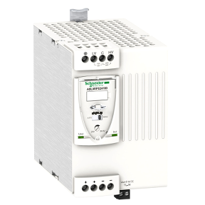
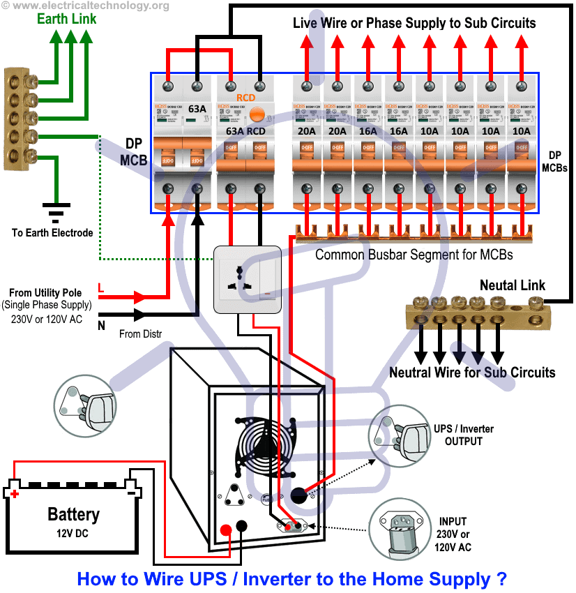
Uninterruptible power supply quint ups 24dc 24dc10 2320225 uninterruptible power supply with iq technology for din rail mounting input. How to do manual auto ups inverter wiring with changeover ats switch. A wiring diagram is a simple visual representation of the physical connections and physical layout of an electrical system or circuit. Assuming your two way switch wiring uses the old core cable colours ie red liv read more. In our previous ups inverter wiring diagrams connections for home we show that how to wire and connect an automatic ups and batteries to the home distribution board for continues power supply. Wiring diagram blaupunkt car stereo.
You may like these posts. Wiring diagram of ceiling fan with regulator. Enter the total load power draw of all devices to be protected by the ups here. I did a continuity test on the 4 wires and wire 1 3 and 2 4 signal as a single wire. Zd1 zener diode 82 volt 05 watt d1 the diode 1n4001 50 volt 1amp t1 transformer 05a 10v b1 aa battery 15v x 5 pcs. 24 v dc output.
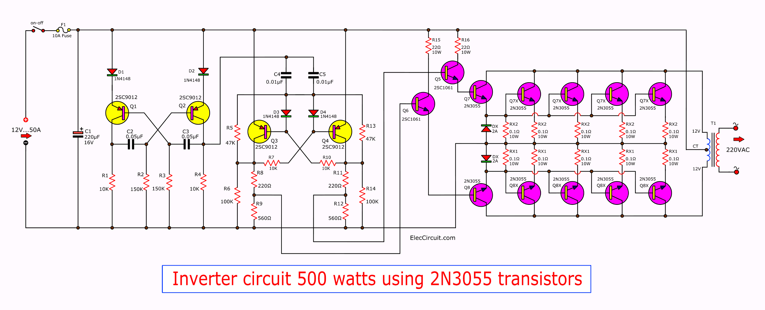
The circuit drawn pertains to a regular industrial ups uninterruptible power supply which shows how the batteries take control during an outage in electrical supply or variation beyond the normal limits of the voltage line without disruption on the operation providing a steady regulated output 5 volts by lm7805 and an unregulated supply 12 volts.


