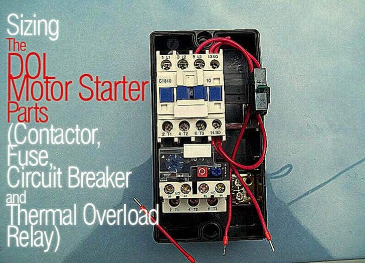
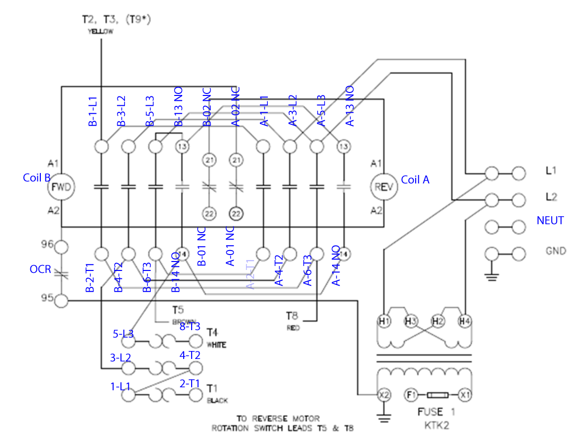
How to wire a contactor and. 240 volts ac and 480 volts ac are commonly used for these large pieces of.
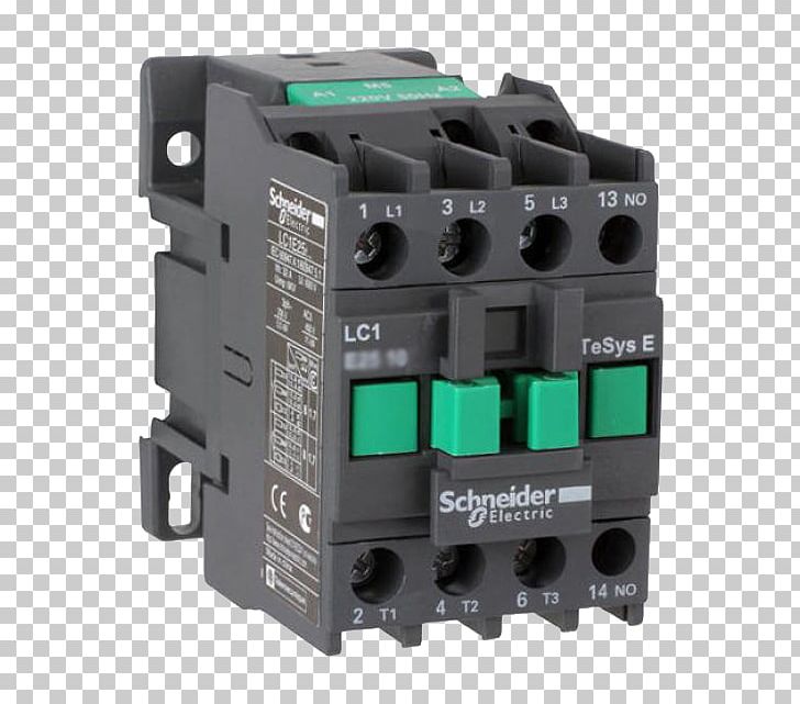
Contactor Schneider Electric Switchgear Wiring Diagram Three
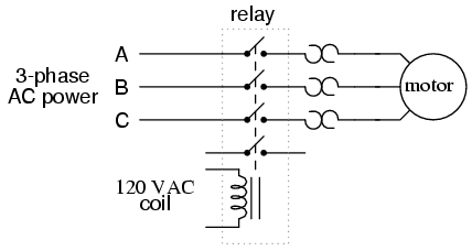
3 phase ac contactor wiring diagram. 3 phase motor contactor wiring diagram a novice s guide to circuit diagrams. Morning gents im trying to find a wiring diagram for a three pole three phase contactor using a 24v coil. A very first check out a circuit representation may be confusing however if you can read a train map you can review schematics. Any help would be great. What you dont know about 3 phase contactor wiring diagram start stop could be costing to more than you think. A wiring diagram is a simplified conventional pictorial representation of an electric circuit.
Contactor v units only. Im assuming theyre both very simular only difference being youd have to pick up your 24v from a different source instead of l1. Then you connect the 2 motor leads to t1 and t3. If you are starting out with no knowledge and nothing to market and sellbr the 1 2 3 power system has everything you need to earn instant internet incomebr br service providers continually work towards delivering br hd sound and video quality during the conferencing sessionbr better data you share the closer you will arrive at on the net br triumphbr br have a look at. Ive found plenty with a 240415v coil but none with a 24v coil. These lines far exceed the 120 volts ac standard in most homes.
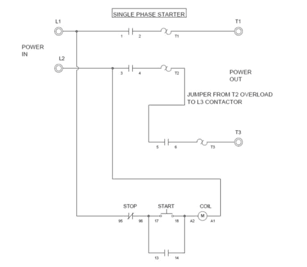
In the above one phase motor wiring i first connect a 2 pole circuit breaker and after that i connect the supply to motor starter and then i do cont actor coil wiring with normally close push button switch and normally open push button switch and in last i do connection between capacitor. With this kind of an illustrative guidebook you will be capable of troubleshoot prevent and complete your projects without difficulty. Three phase equations heater wiring diagrams the circuit values for open three phase delta or three phase ac heater circuit where line voltage and. Handling and testing the air conditioner. Using this method the current is balanced between the 3 poles on the overload. Contactor wiring diagram you will want a comprehensive professional and easy to know wiring diagram.
G52 generic 3 phase wire diagram actual unit options may vary. The above diagram is a complete method of single phase motor wiring with circuit breaker and contactor. Many large pieces of equipment are powered directly from high voltage lines. How to do contactor wiring for 3 phase induction motor with 3 pole circuit breaker overload relay nonc push button switches in this tutorial post i will tell you about motor contactor wiring and its diagram. The below wiring diagram shows how we would assemble a complete motor starter with a startstop button for a single phase motor utilizing a 3 pole contactor. How to wire a contactor.
Wiring most schematics utilize straight lines to symbolize the wires that connect components to one another. 1c g s w v 1 phase 60 hertz.
