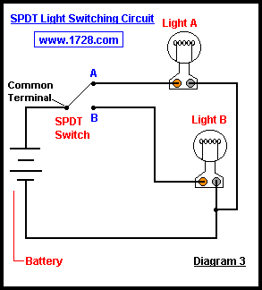
This could be the case at a water well or a workshop. You will need to wire a 240 volt switch using five electrical wires but the job is nearly identical to wiring a standard 120 volt switch.

4 Best Images Of 220 Welder Wiring Diagram 3 Wire 240 Volt
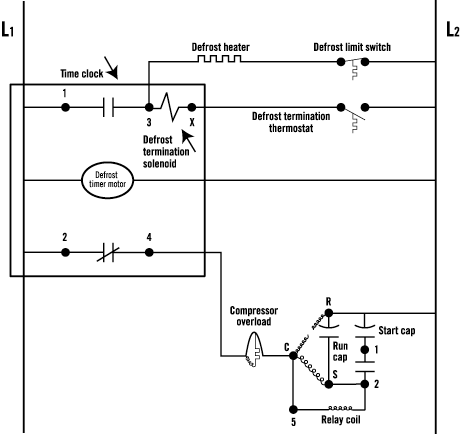
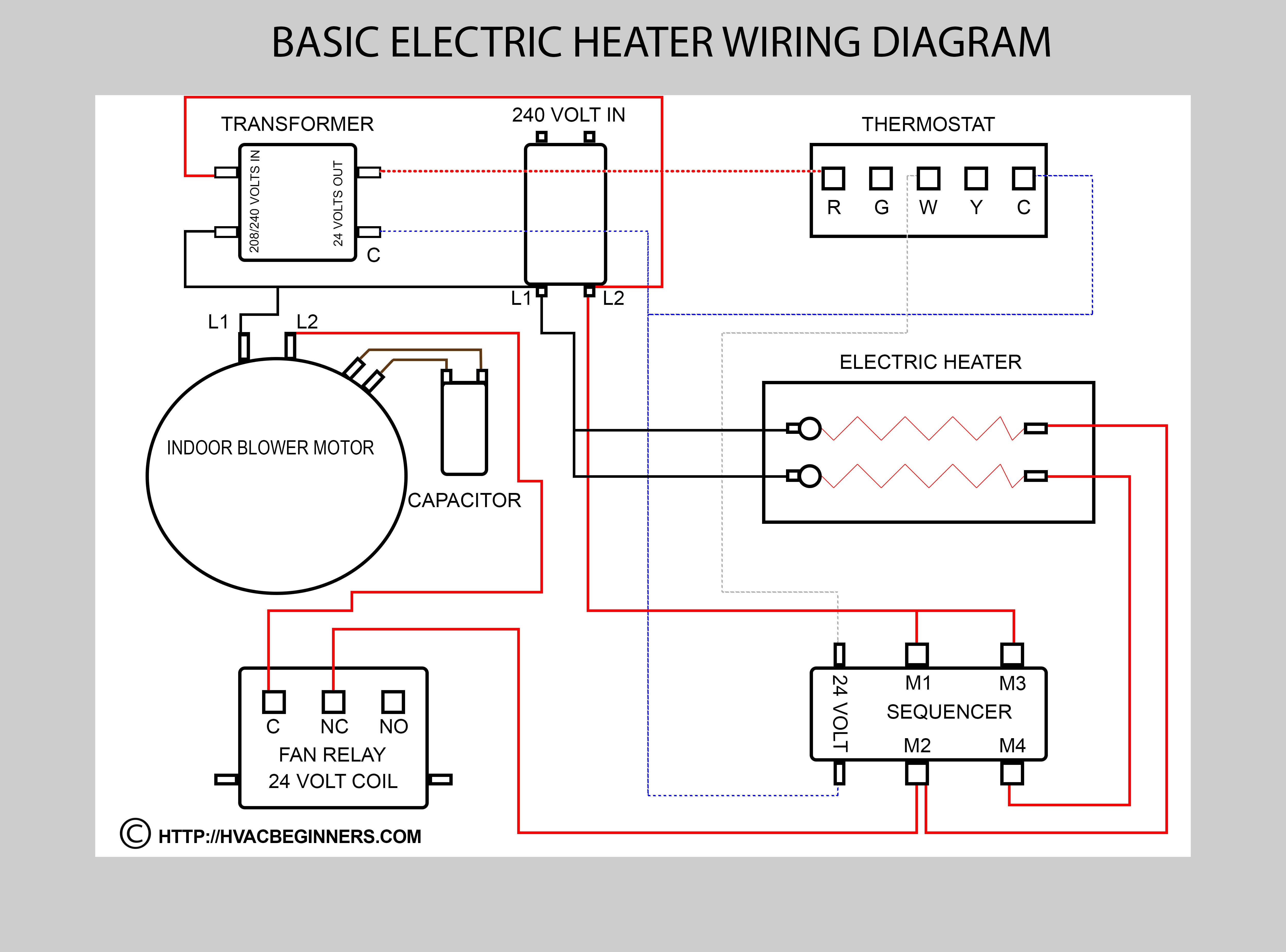
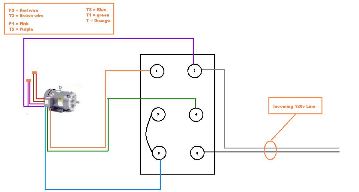
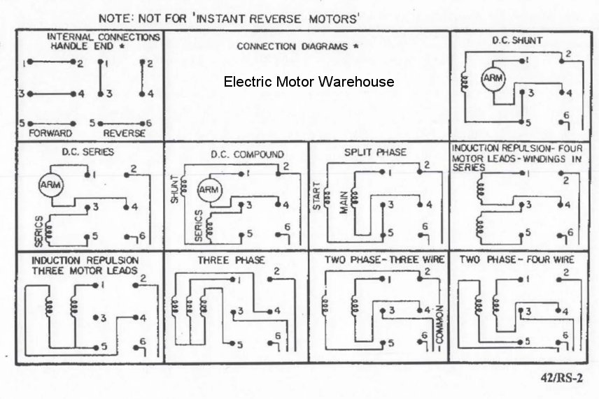
240 volt switch wiring diagram. 240 volt single phase wiring diagram 220 volt single phase motor wiring diagram 220 volt single phase wiring diagram 240 volt single phase motor wiring diagram every electric arrangement is composed of various unique components. Variety of 240v motor wiring diagram single phase. Wiring a 20 amp 240 volt switch can be a confusing experience for the average homeowner used to working with standard 110 volt circuits. This switch doesnt use a neutral conductor. With both conductors carrying 120 volts there is an increased risk of injury or property damage. However a 240 volt switch has two more wires than a standard 120 volt electrical switch so to wire a new 240 volt switch you will have to run two additional wires from the circuit panel.
Otherwise the arrangement wont work as it should be. Each component ought to be placed and connected with other parts in particular way. For one thing both supply wires for this switch carry voltage. A double pole switch is the safest way to make sure that both lines of the 240 volt circuit power to the pump are turned off. A 240 volt circuit is comprised of two hot wires a common neutral wire and a ground wire. It reveals the components of the circuit as simplified shapes as well as the power and also signal connections in between the tools.
A wiring diagram is a streamlined conventional pictorial depiction of an electric circuit. Wiring a 120 volt circuit off of a 240 volt circuit can be useful where there is primarily 240 volts available. Wiring a control switch for a 240 volt pump when controlling a 240 volt motor it is best to install a double pole switch for this irrigation pump.


