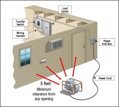
The wires should be drawn through 1 of 3 knockouts located on the underside of the switch. Because the amount of electricity created by a backup generator is not adequate to power all of the electrical circuits in your house youll need to designate a few selected circuits to get backup.

Double Throw Transfer Switch Wiring Diagram Ditinggalrabi
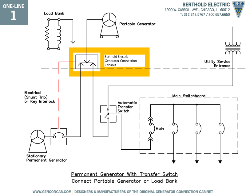
Residential transfer switch wiring diagram. Test your work by first starting up the portable generator. Rxs open transition transfer switches are ideal for residential commercial and light industrial applications. Automatic selective circuit transfer switch retrofitted to 200a residential service. It shows the parts of the circuit as simplified shapes as well as the power as well as signal links between the tools. A wiring diagram is a streamlined standard photographic depiction of an electric circuit. Use the transfer switchs wiring harness to connect the unit to the circuit breaker.
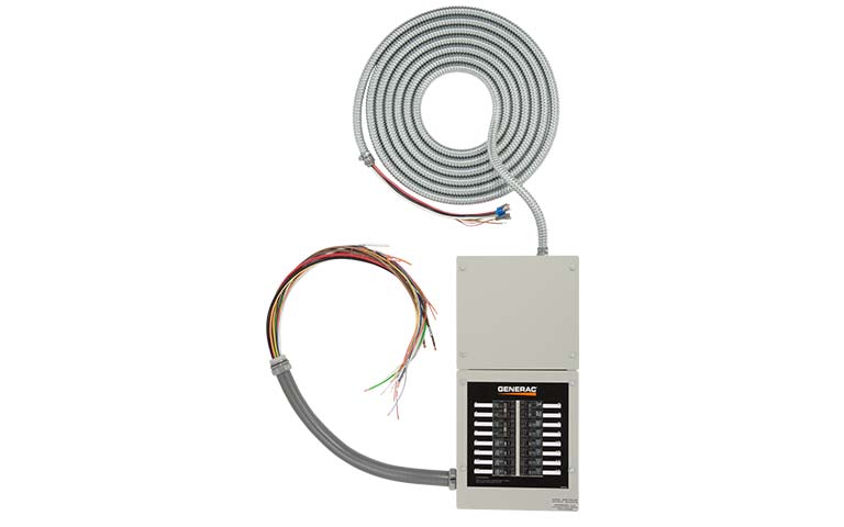
Rxs series transfer switch with the rxs transfer switch you can choose to cover every circuit all the time or only essential circuits when paired with a generator sized to your application. Any existing electrical wiring within the immediate area that may interfere with the installation of the generator transfer switch may need to be relocated if necessary. Collection of residential transfer switch wiring diagram. If utility power fails the switch connects the generators power to the circuits in the generator sub panel. 100 400 spec sheet 600 800 spec sheet. Variety of residential transfer switch wiring diagram.
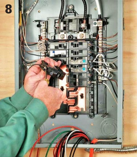
At the outdoors box connect the cable to the electrical receptacle that comes with the transfer switch. Set your store to see local availability add to cart. Screw the receptacle to the box. Installing a generator and transfer switch must be well thought out and performed with a permit with all of the work being inspected. It shows the components of the circuit as simplified shapes and also the power and also signal links in between the tools. Begin a retrofit by mounting the selective circuit manual transfer switch next to the service entrance panel photo 2.
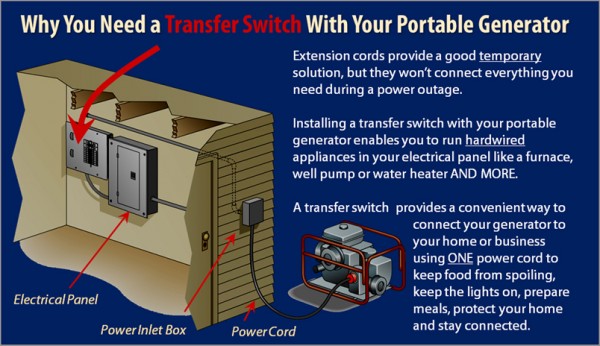
Run an electrical cable from the box to the transfer switch. They should join the circuit breaker through a knockout found at the bottom of the box. Manual transfer switches require an operator to change the power source while automatic switches detect the loss of power start the back up generator and switch over to the backup power feed. Reliance controls 30 amp 250 volt 7500 watt non fuse 6 circuit transfer switch kit model 3006hdk 279 00 279 00. Ge 100 amp 240 volt non fused emergency power transfer switch model tc10323r 139 00 139 00. Move back inside and connect the receptacle cable to the transfer switch.
A wiring diagram is a simplified traditional photographic depiction of an electric circuit. Figure 5 wiring diagram of a manual transfer switch in the on position. When utility power is functioning the wires from the circuit breaker in the main electrical distribution panel are connected to the generator sub panel. Because it is for an optional standby system the owner designates the circuits to be supplied.

