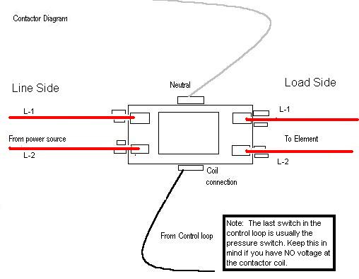
It reveals the components of the circuit as streamlined forms and the power and signal links in between the tools. Variety of 2 pole contactor wiring diagram.

Wiring Magnetic Definite Purpose Starters For Compressor
120 volt contactor wiring diagram. Ac fancompressor not working how to test repair broken hvac run start capacitor air condition hd duration. Contactor breakers limit switch no static control standard elementary diagram symbols. 240 volt motors will have a stronger start compared to a 120 volt motor. The advantages of a 240 volt motor. In other words a 120 volt alternating current commonly referred to as a 120 vac is wired to the coil of the contactor. With all the assist of this e book you can easily do your own personal wiring tasks.
Wiring a 120240 volt motor for 240 volts is as follows. Contactors use 120 volt standard power to energize a magnetic coil which causes a set of internal contacts to close and provide higher power to the equipment. Contactors are used to provide this isolation. These voltages must be electrically isolated from the standard 120 volts ac. Water pump controller with float switch duration. Posted january 18 2018 by springercontrols.
Home about us news wiring a single phase motor through a 3 phase contactor. Ryb electrical 88232 views. Wiring diagram lighting contactor with photocell wiring diagram contactor wiring diagram. Single phase power is typically reserved for lower power requirements however in some cases powering a small motor with single phase input power is practical. Use these tips to learn how to wire a contactor. How to connect a contactor.
To 120 v separate control ot is a switch that opens when an overtemperature. Wiring diagram since wiring connections and terminal markings are. The contactor then uses the set of conductive discs the contacts to supply a 240 vac power source to something like an air conditioner unit or an air compressor. Richard lloyd 2737954 views. 3 phase dol starter control and power wiring diagram. A wiring diagram is a simplified traditional photographic depiction of an electrical circuit.
A balanced electrical load which may save on electricity compared to an unbalanced electrical load. 4 table 2 nema and iec terminal markings. Wiring a single phase motor through a 3 phase contactor. Youll be able to often rely on wiring diagram as an crucial reference that may assist you to save money and time.


