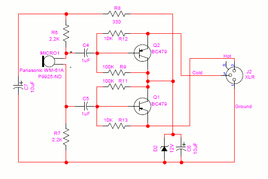
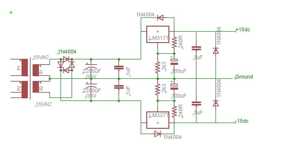
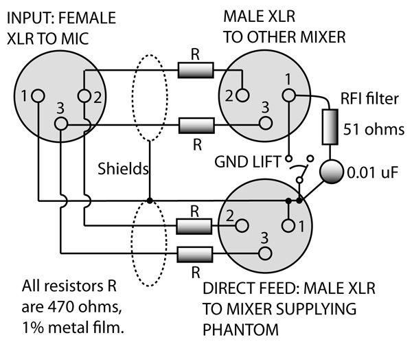
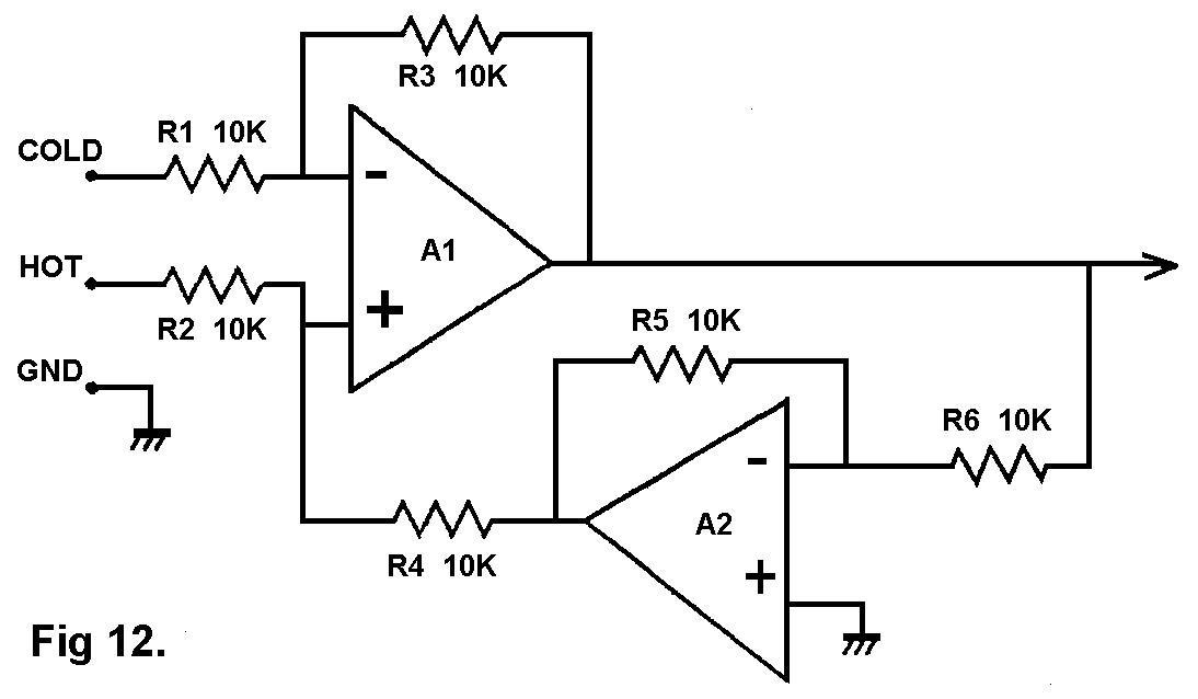
The phantom dc voltage powers the amplification circuitry for condenser microphones and in the case of externally charged capsules phantom. Failing that you can modify your existing mixer using the circuit diagram to provide phantom power for each microphone though be warned this is a specialist job you will need a separate circuit for each microphone and ideally uses 01 or better matched resistors between signal lines and filtered power supply.

Xlr Audio Wiring Diagram Wiring Diagram
Xlr phantom power wiring diagram. The rear view is the end you solder from here are the connections on each pin. Dynamic mic xlr wiring diagram. Pin 2 on the xlr is hot and carries the positive going signal whilst pin 3 is cold and provides the return. Then with a suitable 48 volt dc power supply make the positive and negative connections to the yellow and green wires respectively as shown in figure one. Xlr pinout balanced a balanced system is used in pro audio systems xlr wiring diagram shown below with an overall screen covering a twisted pair. To create a phantom power adapter your project box should include two connectors.
They are most commonly associated with balanced audio interconnection including aes3 digital audio but are also used for lighting control low voltage power supplies and other applications. Phantom power is a 48v dc supplied to the microphone on pins 2 and 3 of the xlr cable while ground is supplied by pin 1. 3 pin xlr connectors are standard amongst line level and mic level audio applications. Phantom power involves a clever scheme that leverages the multiple wires in a typical balanced xlr cable to provide voltage to mics that need it without affecting those that do not. This is a 48v supply in series with about 68k ohms fed to xlr pins 2 and 3 relative to pin 1 which is usually at ground potential. The above diagram shows you the pin numbering for both male and female xlr connectors from the front and the rear view.
The xlr connector is a style of electrical connector primarily found on professional audio video and stage lighting equipmentthe connectors are circular in design and have between three and seven pins. 3 pin xlr wiring standard. You can plug either type of mic into a mixer that provides phantom power and the condenser mic will detect and use the power while the dynamic mic will ignore it. Beware p48 phantom power on professional balanced audio inputs. It figuratively piggybacks on the ac signal and is invisible in operation. Connect the positive negative and ground wires from each xlr connector to the terminal adapter according to the diagram shown.
In the diagram below i show a possible wiring diagram that also takes into consideration the split pair wiring that a properly built rj45 ethernet cable needs to follow. Download dynamic mic xlr wiring diagram. Wire the consumer microphone signal ground to xlr pins 1 and 3 mixer this can either be done as shown in the diagram with a tip sleeve. Dynamic microphone with xlr phantom power electrical engineering stack exchange4 pin dynamic microphone wiring. It is a common way to power professional microphones. A female xlr as mic input and a male xlr to feed the mic signal to the preamp.
The first thing to be aware of is p48 power.
