January 2 2019 february 15 2019. Xlr cable wiring diagram pdf xlr wiring diagram pdf house wiring diagram pdf.
Xlr Microphone Cable Wiring Diagram C3 Wiring Diagram
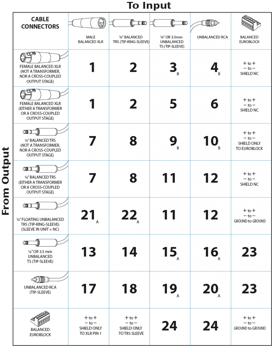
Xlr cable wiring diagram pdf. Van den hul audio cableconnector wiring diagrams female balanced xlr to male unbalanced rca fig. 3 pin xlr audio pinout. 3 pin xlr connectors are standard amongst line level and mic level audio applications. If not the structure will not function as it should be. The next cable insulation is polypropylene about. Convert to pdf professional video connectors are crimped.
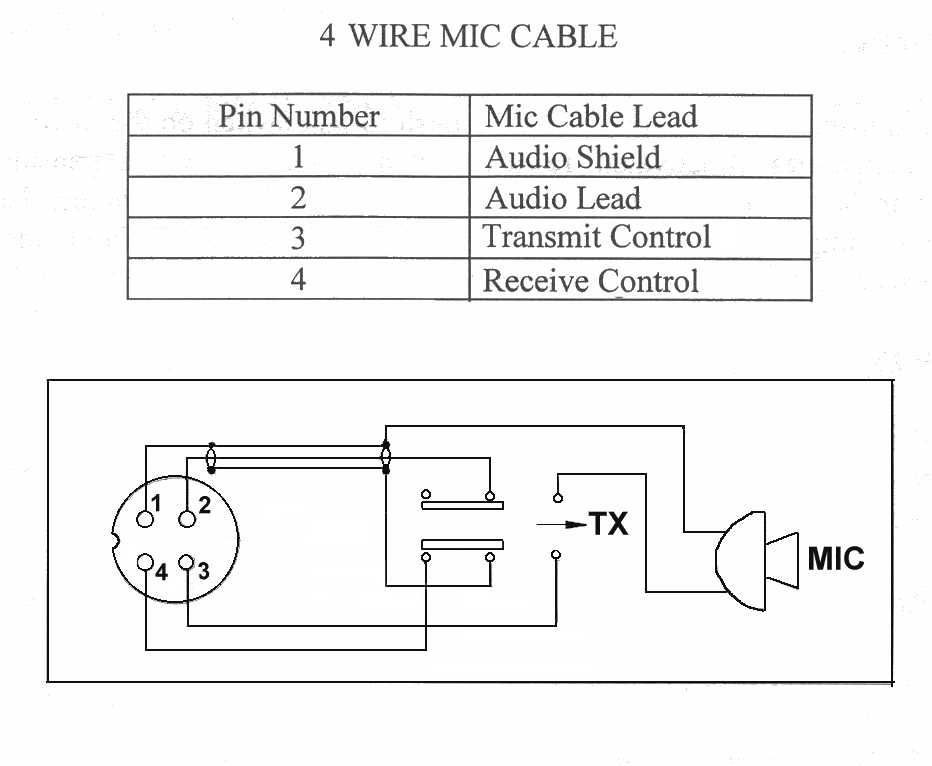
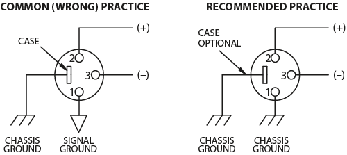
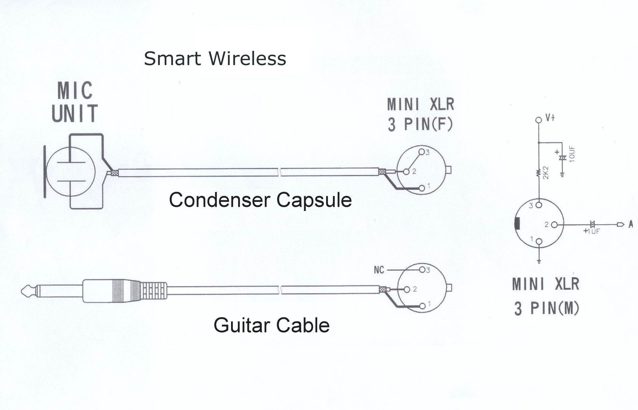
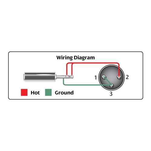
The above diagram shows you the pin numbering for both male and female xlr connectors from the front and the rear view. Xlr wiring diagram pdf xlr cable wiring diagram pdf xlr wiring diagram pdf every electrical structure is composed of various distinct parts. If the signal source is equipped with an output transformer. Some manufacturers especially in vintage equipment do not follow this standard and instead reverse the polarity of pin 2 and 3. The rear view is the end you solder from here are the connections on each pin. But theres one professional connector that is still soldered the venerable xlr.
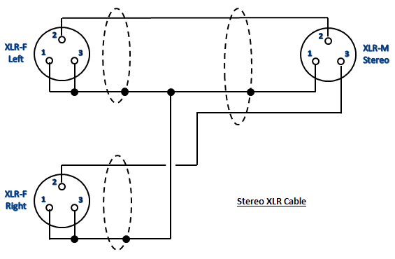
To properly wire a balanced to balanced cable using 4 conductor starquad and maximise noise rejection opposing conductors are terminated together into an xlr 3 connector or terminal block. Starquad wiring for balanced xlr to xlr connections. The surrounding shield should be soldered to pin 1. If the signal source is equipped with a cross coupled output stage. 3 pin xlr wiring diagram cable wiring etc cable designed for being cut into standard mic cables may have 2 pairs of wire and a shield around the outside in that case pair the colors together and make sure they go to the same pin number on each end. 3 pin xlr wiring standard.
It shows the elements of the circuit as simplified forms and the power and also signal connections between the tools. Collection of xlr wiring diagram pdf. It has become the universal standard for audio wiring. As the diagram below shows the four conductors are arranged in a cross formation the conductors. Each component ought to be placed and linked to different parts in specific way. The following is the aes industry standard for balanced audio xlr wiring commonly known as pin 2 hot.
3 pin xlr wiring diagram cable wiring etc cable designed for being cut into standard mic cables may have 2 pairs of wire and a shield around the outside in that case pair the colors together and make sure they go to the same pin number on each end. A wiring diagram is a simplified standard photographic depiction of an electric circuit. Steve lampen 7612 soldering mic connector xlr balanced lines. If the signal source is equipped with a pseudo balanced output stage. Wiring up an xlr.


