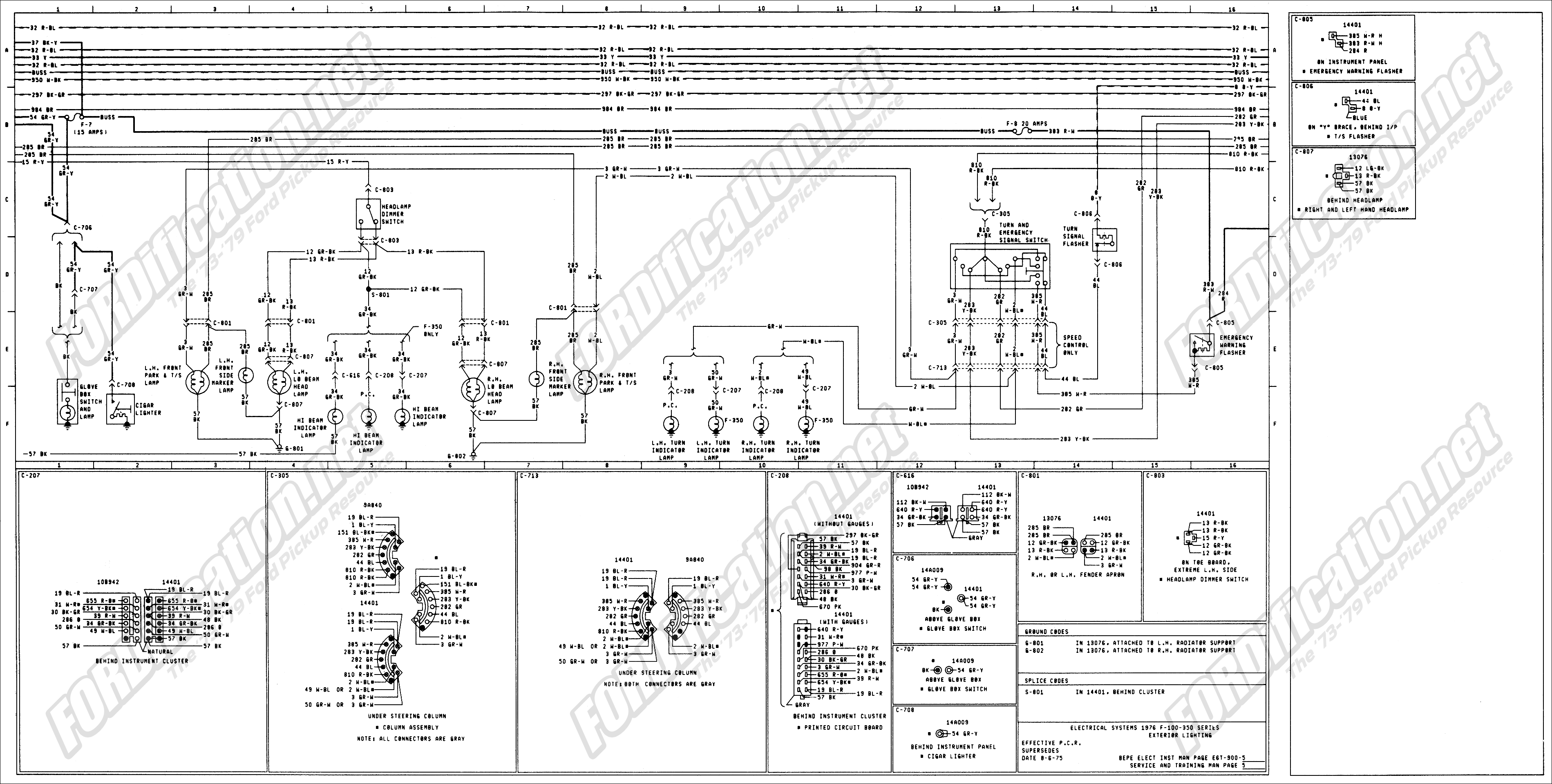
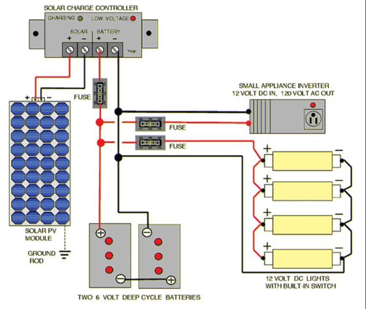
Trane condensing unit wiring diagram trane xr14 installation throughout trane xe1000 wiring diagram image size 600 x 279 px and to view image details please click the image. A wiring diagram is a type of schematic which makes use of abstract photographic signs to show all the affiliations of elements in a system.

Ge Range Wiring Diagram Wiring Diagram
Wiring diagram or schematic. It shows the components of the circuit as simplified shapes and the power and signal connections between the devices. Resistors on a schematic are usually represented by a few zig zag lines with two terminals extending outward. Wiring layouts are made up of 2 things. Wiring diagrams show how the wires are connected and where they should located in the actual device as well as the physical connections between all the components. Here are some of the standardized basic schematic symbols for various components. A schematic shows the plan and function for an electrical circuit but is not concerned with the physical layout of the wires.
A wiring diagram is a simplified conventional pictorial representation of an electrical circuit. How is a wiring diagram different from a schematic. A wiring diagram usually gives information about the relative position and arrangement of devices and terminals on the devices to help in building or servicing the device. Parts that are shown broken down into their sub components for the schematic retain their complete package format for the wiring diagram. Here is a picture gallery about trane xe1000 wiring diagram complete with the description of the image please find the image you need. Schematic symbols part 1 are you ready for a barrage of circuit components.
Icons that stand for the components in the circuit and lines that represent the connections between them. They are crucial to the assembly of the circuit or system. The most fundamental of circuit components and symbols. Wiring diagrams or layouts illustrate the physical connections or wiring between components.


