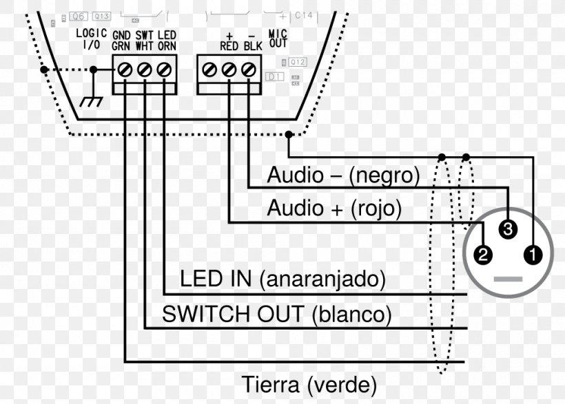
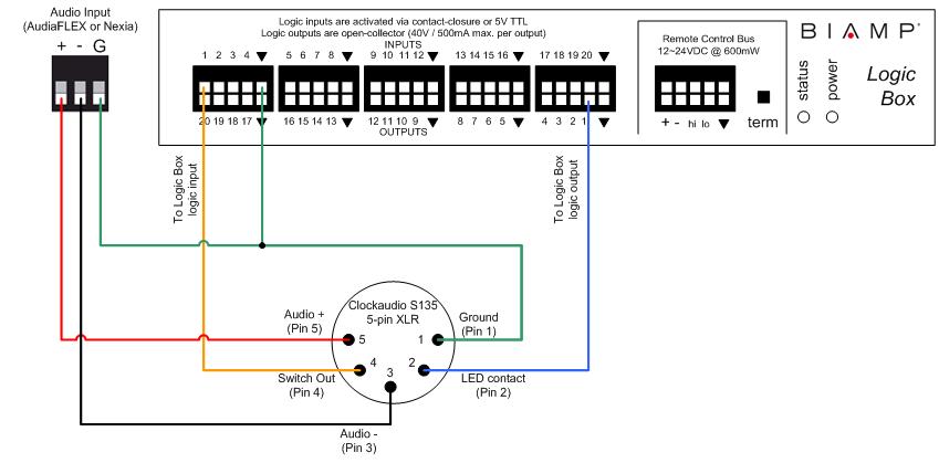
A wiring diagram is a simplified standard photographic depiction of an electric circuit. I checked my two reference cable and it was connected pin t.

Soldering Xlr
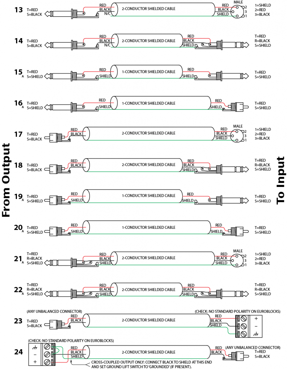
Wiring diagram for xlr connector. 3 pin xlr wiring diagram cable wiring etc cable designed for being cut into standard mic cables may have 2 pairs of wire and a shield around the outside in that case pair the colors together and make sure they go to the same pin number on each end. The audio signal is carried in anti phase on the positive and negative wires and this is decoded at the. The ts connector is an unbalanced connector. Xlr pin 3 battery negative. How to wire an xlr connector balanced a balanced system is used in pro audio with an overall screen covering a twisted pair. Xlr pin 2 inhibits vehicle operation when pulled to battery negative.
Xlr pin 1 battery positive. Some manufacturers especially in vintage equipment do not follow this standard and instead reverse the polarity of pin 2 and 3. The positive and shield of the xlr are joined together either at the xlr end or the rca end. 3 pin xlr audio pinout. Collection of xlr wiring diagram pdf. The above diagram shows you the pin numbering for both male and female xlr connectors from the front and the rear view.
According to my amplifiers guide the proper wiring for my preamp to amplifier is to have the xlr cable pin 1 not connected to pin 1 at the amplifier end. The easiest way is to solder a link between pins 1 and 3 shield and negative of the xlr rather than trying to solder the shield and negative wire to the sleeve contact of the rca. 3 pin xlr wiring standard. The trs connector can be used for many things including balanced audio sendreturn for insert points and leftright stereo just to name a few. Xlr to ts 14 connecting a balanced xlr connector to. Pin 2 just lets the unit sense when the charger is connected and disables the drive so you dont run away with the charger cord attached.
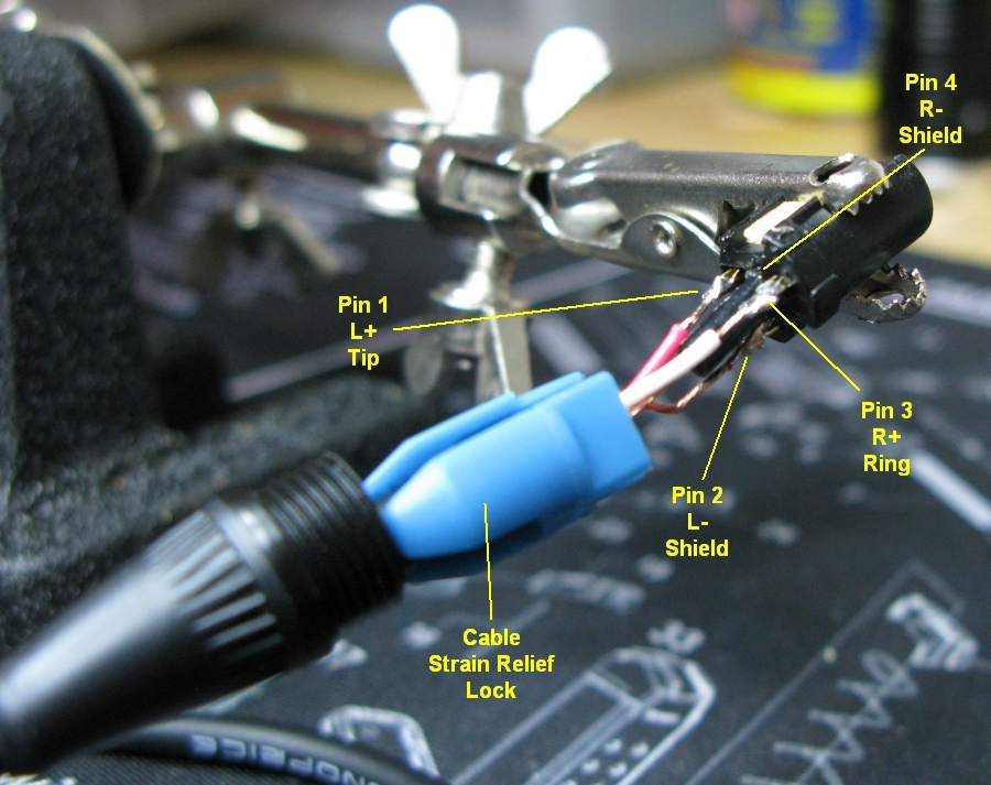
The three terminal 14 connector is commonly referred to as the trs or tip ring sleeve version. Pin 2 on the xlr is hot and carries the positive going signal whilst pin 3 is cold and provides the return. The surrounding shield should be soldered to pin 1. Customarily the shieldground copper wire is always going to be associated with 1 the positively charged red or blue wire associated with 2 and the negatively charged white blue or green or black wire associated with 3note. It shows the elements of the circuit as simplified forms and the power and also signal connections between the tools. This produces an unbalanced audio cable.
The rear view is the end you solder from here are the connections on each pin. If theres a white wire inside your cable your positive end will be red or blue if theres a blue wire with no white wire your positive end will be red. The following is the aes industry standard for balanced audio xlr wiring commonly known as pin 2 hot. Unless the source is 2 wire ac supply the pin 1 should not be terminated to pin 1. 3 pin xlr connectors are standard amongst line level and mic level audio applications.


