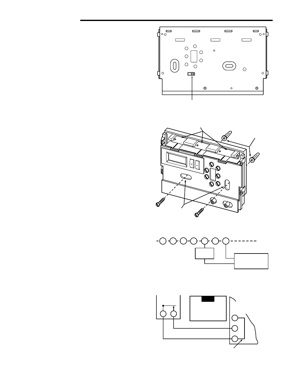
The old tstat had red to red white to white and the green wire attached to the y terminal on a honeywell series 20 tstat. December 27 2018 by larry a.

Locating C For Ecobee Install With Zone Valves Doityourself
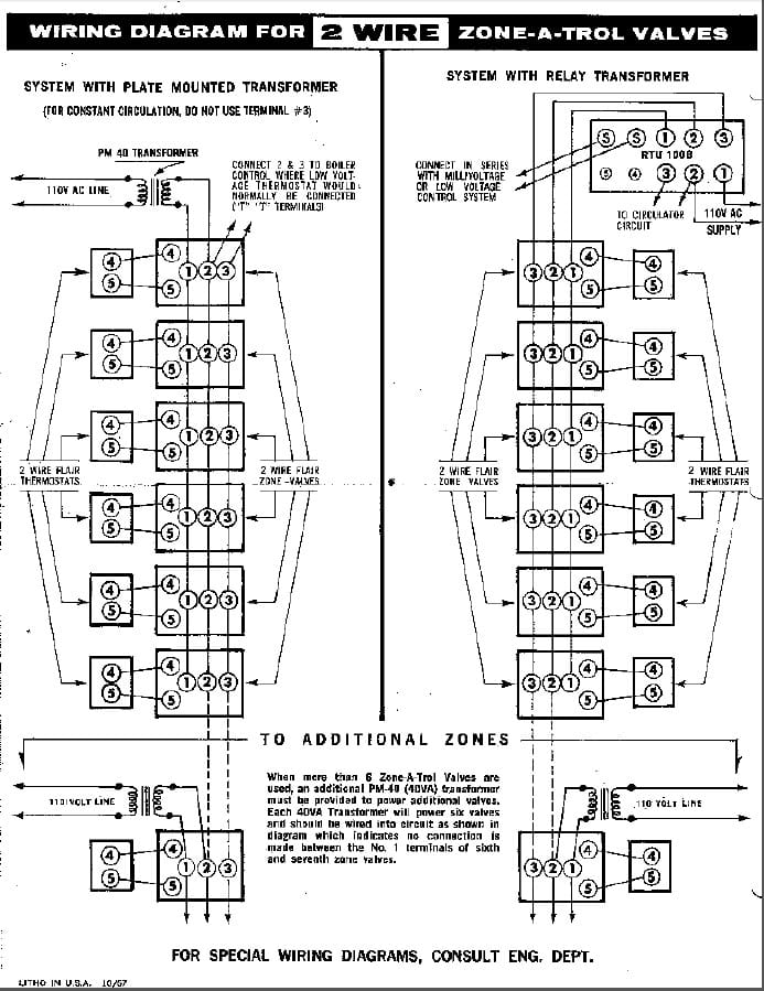
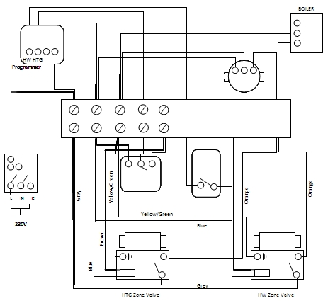
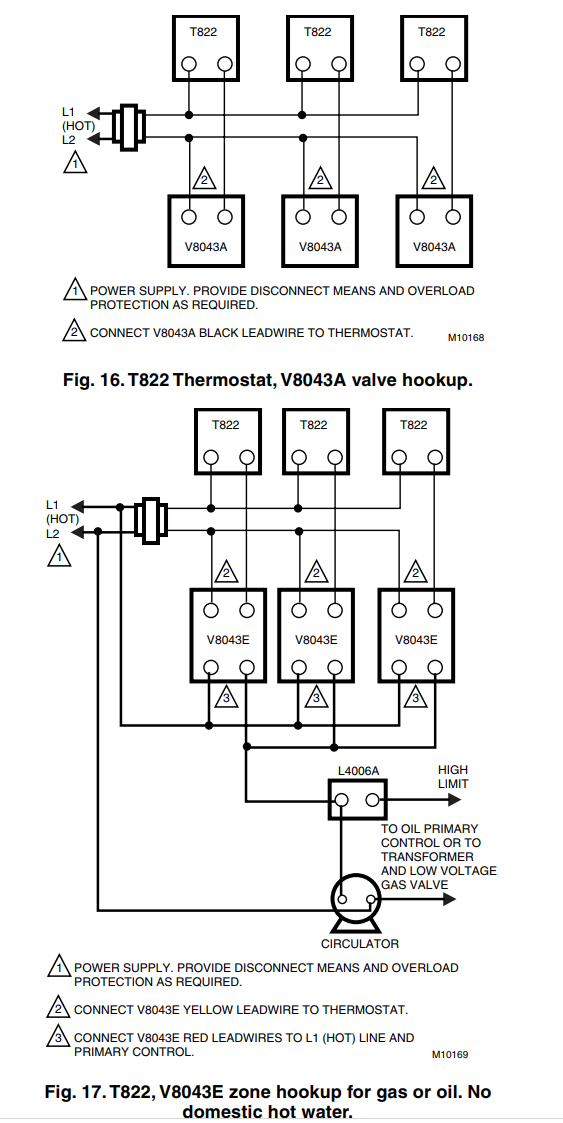
Wiring diagram for white rodgers zone valve. It shows the elements of the circuit as simplified shapes and the power and signal links in between the tools. A wiring diagram is a streamlined conventional pictorial depiction of an electrical circuit. Wellborn variety of white rodgers gas valve wiring diagram. White rodgers 1311 102 wiring diagram collection dorable 3 wire zone valve thermostat ponent electrical and. It reveals the components of the circuit as streamlined shapes and the power and signal connections in between the tools. White rodgers 3 wire zone valve wiring diagram likewise white white rogers thermostat wiring diagram.
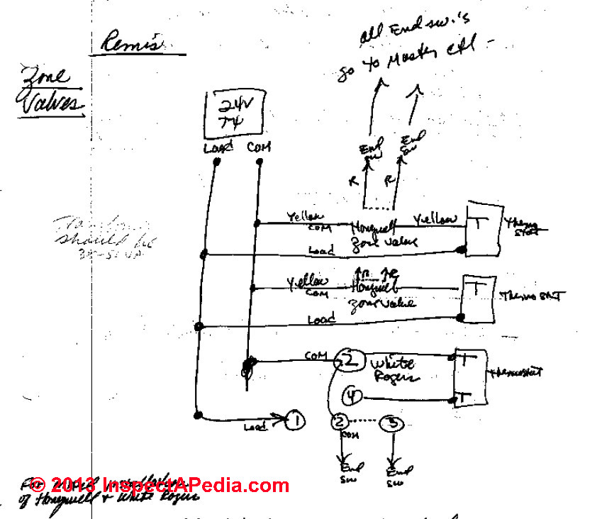
White rodgers zone valve wiring diagram if you have a white rodgers heat pump and thermostat system or an emerson thermostat the wiring likely follows a particular pattern. Ecobee3 lite with wire zone valves to ecobee wiring diagram room. White rodgers zone valve wiring diagram. Taco zvc403 4 wiring diagram unique great zone valve wiring diagram. Wiring diagram taco zone valve wiring diagram unique carrier duct. A wiring diagram is a simplified conventional photographic depiction of an electric circuit.
Wiring diagram for zone valves free download wiring diagram. This article describes how to wire up heating zone valves. Hot water heating system zone valve installation. We include wiring diagrams and installation instructions for most zone valve model and multi zone controllers and we describe special wiring problems that can occur if you mix different types brands or models of heating zone valves on the same hydronic heating hot water heating system. Good taco zone valve wiring diagram 73 in honeywell fan limit switch. Ac service tech llc 43698 views.
Taco zone valve wiring voltage and water flow tested and provedthe water in the top falls through. Stunning white rodgers gas valve wiring diagram. If same trans former powers both the auxiliary circuit and the water valve connect auxiliary cir cuit to terminals 1 and 3 instead of 2 and 3 transformer internal wiring external wiring motor holding contact. Trane heat pump wiring diagram 90 340 relay wiring diagram wiring diagram centre we collect lots of pictures about white rodgers zone valve wiring diagram and finally we upload it on our website. Many good image inspirations on our internet are the very best image selection for white rodgers zone valve wiring diagram. It makes the process of assembling circuit easier.
However the diagram is a simplified variant of the arrangement. Wellborn assortment of white rodgers zone valve wiring diagram. The diagram offers visual representation of the electrical structure. July 12 2018 by larry a. White rodgers zone valve wiring diagram.


