A three wire three phase circuit is usually more economical than an equivalent two wire. It is also used to power large motors and other heavy loads.

How To Wire 3 Phase
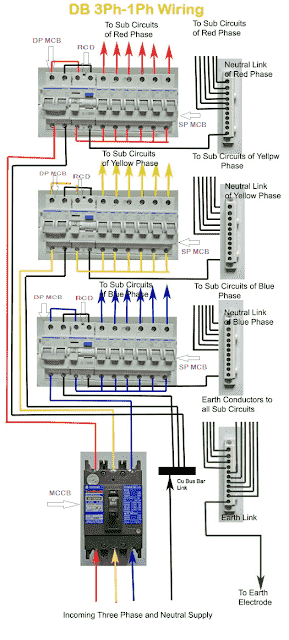
Three phase electrical wiring diagram. This video explains the basics of installing the eg3000 in a three phase distribution panel defines each incoming line. Three phase power from the utilities is connected to the main breaker through three phase energy meter. The star delta y δ 3 phase motor starting method by automatic star delta starter with timer. The neutral wire serves as common return to all the three phases acting outward from n 1. In the united states for low voltage motors below 600v you can expect either 230v or 460v. Three phase installation tutorial for the egauge eg3000 energy meter.
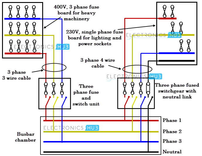
The neutral points in both alternator and the load are joined together. The figure below shows schematic diagram for industrial three phase wiring. The difference between single phase three phase electrical wiring. How to wire a single phase kwh meter digital or analog energy meter from the supply to the main distribution board mdb. There is no such thing as two phase power which is a surprise to some people. Electrics induction motors use all three phases of the power without any neutral wire.
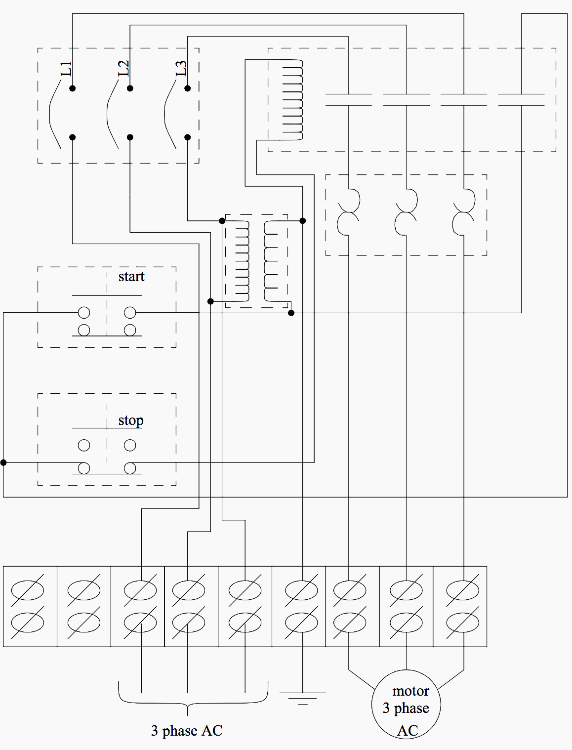
The other type of three phase power is three phase motor wiring. In our today electrical wiring installation tutorial we will show how to do a three phase consumer unit installation from utility pole to a 3 phase energy meter 3 phase distribution board and then how to connect single phase three phase loads in a three phase wiring distribution system in home electric supply system. A three phase motor circuit is nearly as efficient as a dc supply. To make the transformer connections compatible with three phase supplies we need to connect them together in a particular way to form a three phase transformer configuration. Room air cooler wiring diagram 2. Busbars carries this three phase power and from which individual connections are brought out to individual loads through cables.
The first step is to figure out the voltage of your phases. A transformer can not act as a phase changing device and change single phase into three phase or three phase into single phase. That being said there is a wide range of different motors and what you have on hand can be completely different. Each of the three phase wires connects to a specific motor lead. It is a type of polyphase system and is the most common method used by electrical grids worldwide to transfer power. Three phase electrical wiring installation in a multi storey building.
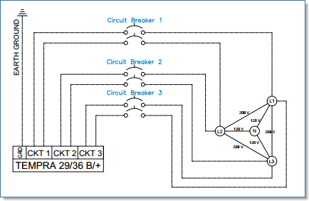
In the above diagram the alternator is connected to the load by three phase four wire system. Three phase electric power is a common method of alternating current electric power generation transmission and distribution. V l is the line to line voltage and v p is the phase to neutral voltage. Single phase power is commonly called. A three phase motor must be wired based on the diagram on the faceplate. Therefore the total neutral current is the vector sum of the three line currentsunder balanced conditions the vector sum is zero and.
The difference between three phase and single phase is primarily in the voltage that is received through each type of wire.

