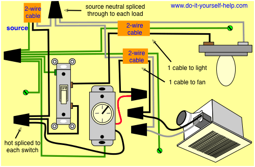
Assortment of bathroom fan with timer wiring diagram. Instead we are going to install a new switch that will turn teh fan on and off.

Wiring Diagram For Inline Extractor Fan With Timer
Wiring diagram for bathroom extractor fan with timer. Wiring of timer model. I have tried unlinking the blue wire covered with the brown and. Requiring a live and neutral supply refer to internal wiring label for correct connection. Refer to internal wiring label and diagram 2. This wiring diagram shows an easy to follow configuration for a bathroom extractor fan fitted with a timer thats not going to be turned on by the existing light switch. A wiring diagram usually gives suggestion just about the relative approach and promise of devices and terminals upon the devices to incite in building or servicing.
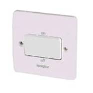
Hi dave thanks for the response yes there is an isolator above the bathroom door which turns off the lights and presumably the fan when it works. In straight forward terms how are the three parts wired. A shower extractor fan is essential in a room containing a shower in order to prevent. Fans like this require additional wiring as both a permanent live and switched live are required as the fan has a built in timer so that it continues to extract air for a set period of time after the light in the room has been switched off. The bathroom lights are operated from a pull switch the isolator switch is adjacent to the pull switch on the corridor side of a stud partition. This fan requires a neutral switch live and permanent live supply.
Here is the. John corbett apr 27 2019 1. Bathroom fan with timer wiring diagram wiring diagram for bathroom fan with timer 2019 wiring diagram bathroom extractor fan new wiring diagram. Manrose fan wiring diagram wiring diagram is a simplified adequate pictorial representation of an electrical circuitit shows the components of the circuit as simplified shapes and the gift and signal links between the devices. Since the relay coil may produce unwanted voltage spikes into the circuit wiring which may damage the electronics in some fan units some effort has been made to suppress these. Suitable for ceiling fixing.
Three core and earth has been run from the pull switch to the extractor fan. This fan has its own integral pullcord onoff switch. In this case a common 01uf100 ohm rc mains input suppressor as well as a 250vac metal oxide varistor mov transient suppressor were used in parallel.


