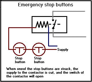
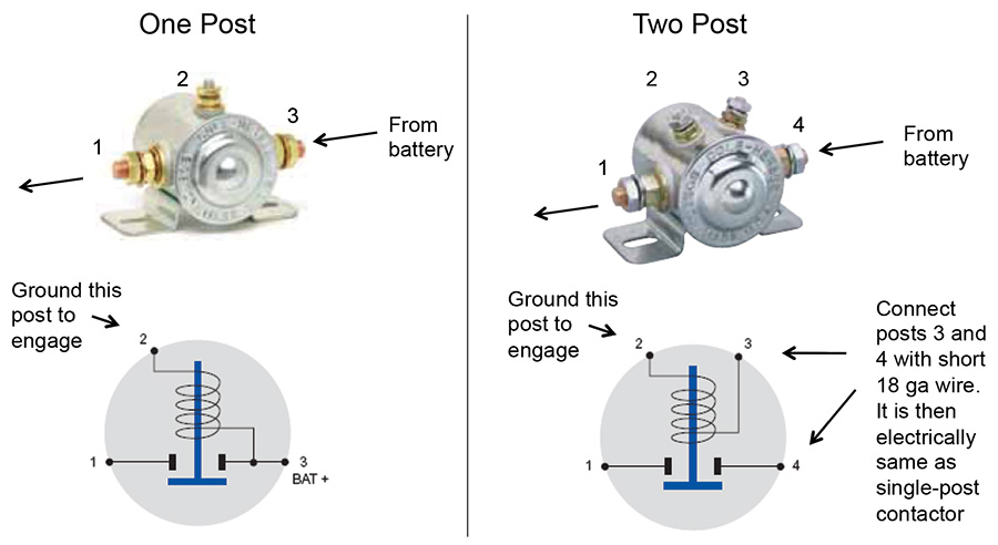
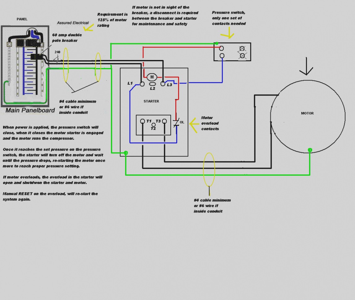
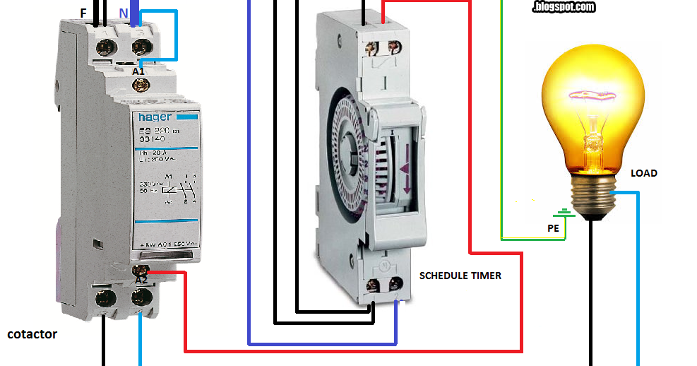
This contactor draws about 4a at 14v. Variety of 2 pole contactor wiring diagram.
Dannmar Two Post Lift Wiring The Garage Journal Board
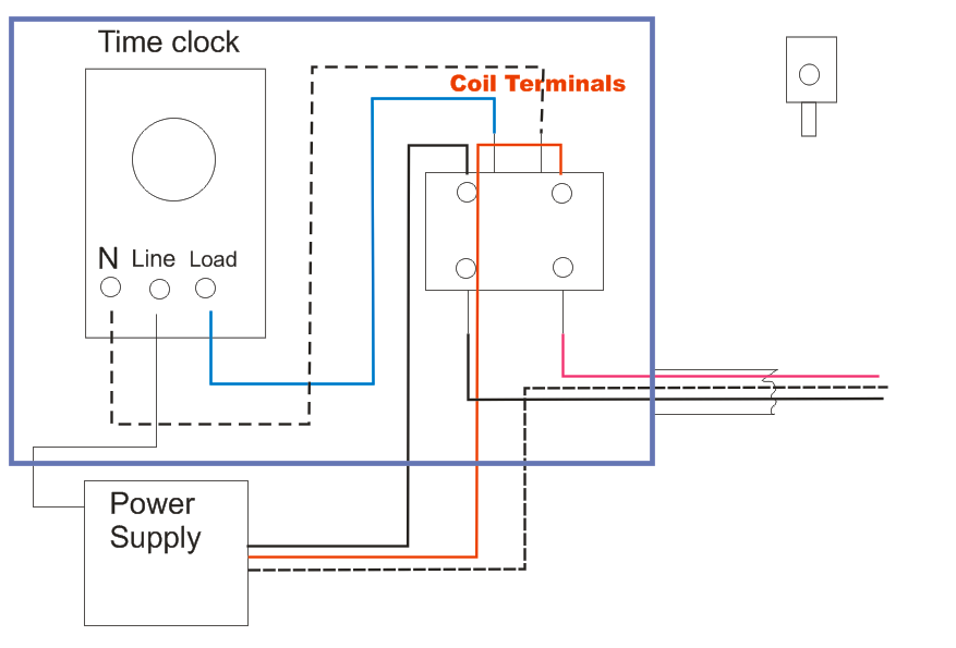
Wiring diagram for a contactor. Wiring diagram since wiring connections and terminal markings are shown this type of diagram is helpful when wiring the. The black power wires will need to be tied together. Power power coil gets ground from mounting bracket. Contactor wiring diagram https. Lighting contactor wiring diagram with cell westmagazine net. Water pump controller with float switch duration.
The contactor will have space for the red power wires coming in from the photocell circuit breaker and lights. It reveals the elements of the circuit as streamlined forms and the power and also signal links between the gadgets. How do i do a wiring to a single phase contactor via photocell to the outside lights. Ryb electrical 88232 views. Starter contactor starter contactor aka starter relay is an intermittent duty relay meaning it is designed to be turned on only for short periods of time. This is a common type of contactor sold by vans aircraft and others.
3 phase dol starter control and power wiring diagram. Water pump controller with float switch duration. It reveals the components of the circuit as streamlined forms and the power and signal links in between the tools. Contactor wiring diagram you will want a comprehensive professional and easy to know wiring diagram. Magnetic contactor circuit diagram luxury thermal overload relay. The lights connect to the output ports on the contactor.
3 phase dol starter control and power wiring diagram. Contactor wiring diagram pdf download furnas contactor wiring diagram download. To read a wiring diagram first you must know what fundamental elements are included in the wiring diagram and which pictorial symbols are utilized to represent them. Collection of ac contactor wiring diagram. Contactor breakers limit switch no static control standard elementary diagram symbols. A wiring diagram is a simplified traditional photographic depiction of an electrical circuit.
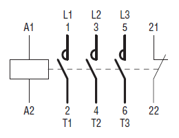
The common elements in the wiring diagram are ground energy wire and connection output devices switches resistors logic gate lights etc. How to connect a contactor. With this kind of an illustrative guidebook you will be capable of troubleshoot prevent and complete your projects without difficulty. 4 table 2 nema and iec terminal markings. A wiring diagram is a simplified traditional pictorial representation of an electrical circuit. Iec contactor wiring diagram bureaucraticallyfo.
Ryb electrical 82696 views.

