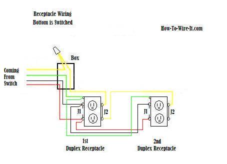
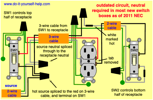
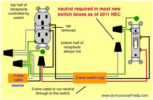
Wall switch and outlet electrical question. Switched split outlet wiring diagram for controlling the half of two duplex electrical receptacles by a wall switch without a neutral conductor.
How To Install Wall Outlet On A Switch The Home Depot Community
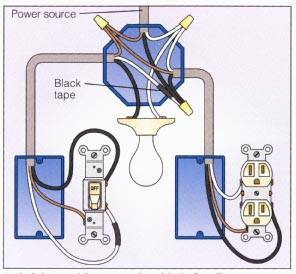
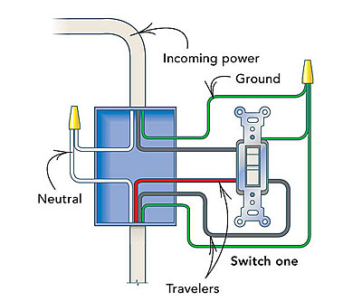
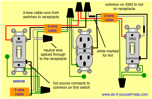
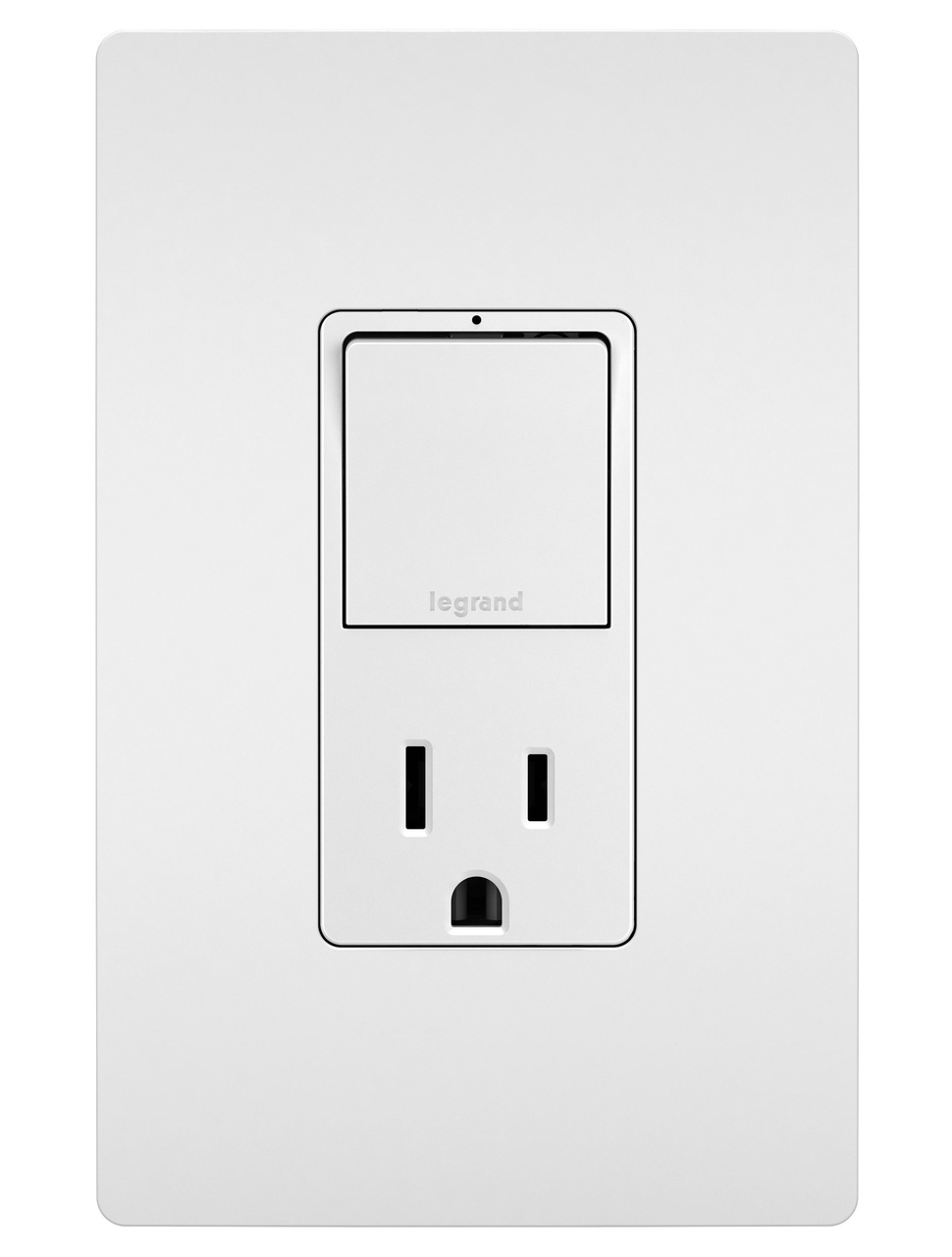
Wall switch outlet wiring diagram. The diagram below shows the power entering the circuit at the grounded outlet box location then sending power up to the switch and a switched leg back down to the outlet. I am trying to install a combo switch outlet to an original single switch box. The switch takes the hot from the middle receptacle here and 3 wire cable runs from there to the new switch location. Here a switch has been added to control an existing receptacle. My light switch wiring diagrams may be helpful to you. Three wire cable runs between the switches and the outlet.
The hot source at the outlet is spliced to the black wire running to the switch and the hot wires running to the other outlets in. 3 way switched outlet wiring. Or if the top and bottom outlets of a duplex receptacle are powered by two different circuits the hot tab and possibly the neutral tab will be removed. If one half of a duplex outlet is controlled by a wall switch then the hot tab and possibly the neutral tab will be broken off. The switch will control the lights over two sinks and the outlet to be always hot. I have three pieces of pipe coming into the junction box and i have a black and a white white one has black and white wire and an orange wire.
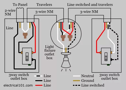
In this diagram two 3 way switches control a wall receptacle outlet that may be used to control a lamp from two entrances to a room. This circuit is wired the same way as the 3 way lights at this link. Wall outlet switch wiring diagram. Also shown is the half of the receptacle that is live at all times and the tab that must be cut in order to split the receptacles. Notice that these outlets have the tab removed from the hot side or brass side of the outlet which allows the top half of the plug to be controlled only from the switch.
