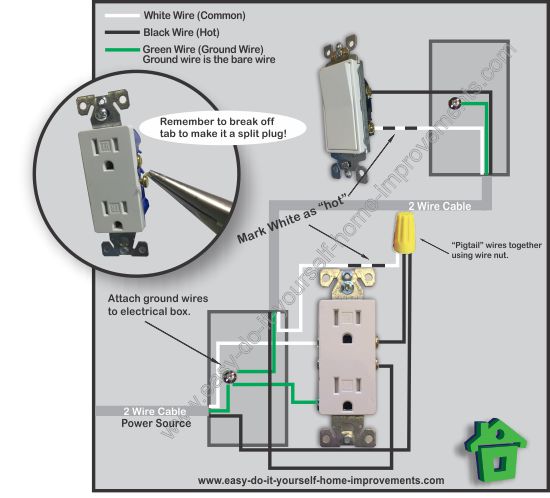
The green screw obviously ties to the bare ground wire. The hot source wire is removed from the receptacle and spliced to the red wire running to the switch.

Wiring Up A Bathroom Exhaust Fan How To Instructables
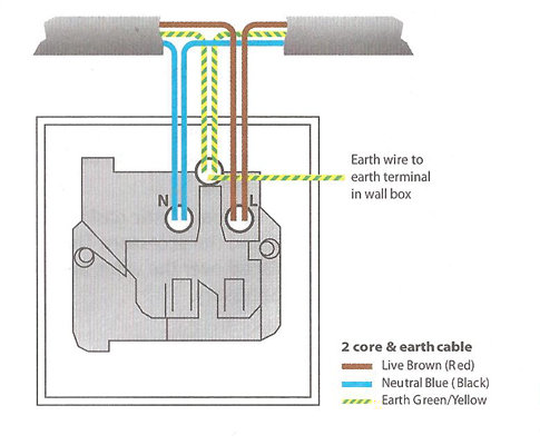
Wall plug wiring diagram. Bare the ends of the three wires inside the electrical cord for about half a centimeter by cutting away the plastic insulation. The key is to make sure you connect the wires to the proper terminals in the plug. Remove the plug cover by either snapping or unscrewing it. Each component should be placed and connected with other parts in particular manner. Before touching any bare wires or terminals on a switch or outlet use a voltage tester on all the wires to make sure the power is off. The source is at the outlet and a switch loop is added to a new switch.
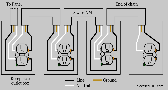
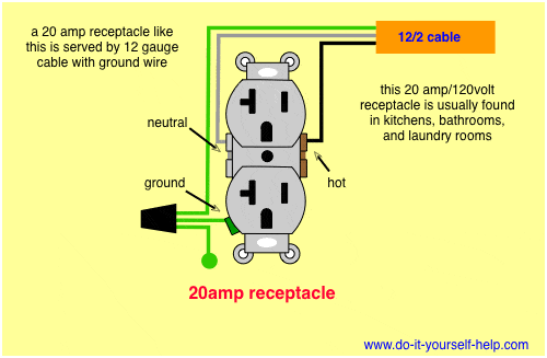
Fully explained pictures and wiring diagrams about wiring light switches describing the most common. The hot black wire should connector to the brass colored screw. The worry is that a miswired plug poses a fairly serious shock hazard. How to use wall plug power for wiring light fixtures. This is a standard 15 amp 120 volt wall receptacle outlet wiring diagram. The long slot on the left is the neutral contact and the short slot is the hot contact.
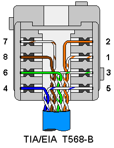
This is a polarized device. The hot wire goes on the brass terminal screw the white wire goes on the chrome one and the ground wire goes on the green one. A ul knot secures the cord. In 110v plug wiring youre dealing with 14 or 12 gauge wire. Yes steve and you will see how in the switch wiring diagrams found below. Ethernet wall socket wiring diagram ce tech ethernet wall plate wiring diagram ethernet wall jack wiring diagram ethernet wall plate wiring diagram every electrical structure is made up of various diverse pieces.
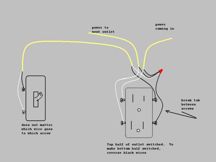
This telephone wiring diagram with photos and instructions will show you the direct steps to correctly wiring a telephone jack. If not the structure wont function as it ought to be. Wiring a light switch diagram 1. There is a tab between each of the screws of similar color. Wiring an outlet to a switch loop. Wiring a telephone jack after installing the cat 3 3 pair phone wire i am ready to install the wall jack.
This wiring diagram illustrates adding wiring for a light switch to control an existing wall outlet. When wiring a wall outlet the neutral white wire should connect to the white or silver metal screw. Wiring a plug. Telephone wiring diagram for home telephone jacks. Fold over the twisted strands. Before you tackle any part of this project turn off the power to the circuit at the main electrical panel by switching off the breaker or removing the fuse.
If youre wiring a 3 prong plug you need 2 conductor cable with a ground. You will have a wide variety of telephone jacks to. The following will assist you with wiring light fixtures. The danger isnt fire. Standard wall outletreceptacle wiring. A grounded contact at the bottom center is crescent shaped.
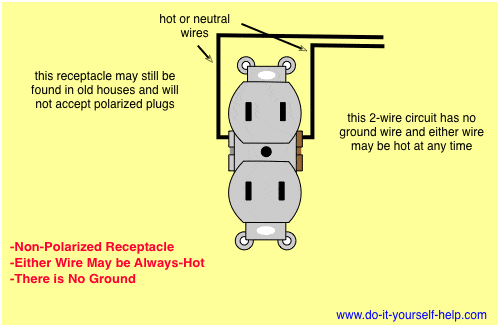
Wire a plug to maintain correct polarity. Gently twist the strands of copper wire with your fingers until each strand is tight. Dont use this receptacle when no ground wire is. Wiring a new plug isnt difficult but its important to get the hot and neutral wires connected to the proper prongs. Wiring a grounded duplex receptacle outlet.


