If you love my content and would like to send me a couple of to help me to keep creating. Lutrons new facility management tool empowers you to manage your building from anywhere.

Nz 5777 Varilight Hn3 Halogen 400 Watt With Dimmer Switch
V pro dimmer wiring diagram. A device like this should only be used with an incandescent light fixture. A comprehensive buying guide that you must read if you are wondering how to dim your gu10 led lamps. Wiring between the rear of the dimmer and the back of the wall box. If you experience flicker in the low end range of dimming the low end trim adjustment can be used to improve performance. Circuit electrical wiring enters the switch box. Featuring wiring diagrams for single pole wall switches commonly used in the home.
Explanation of wiring diagram 1. Many manufacturers are now producing dimmer switches that can be used for either single pole or 3 way switches. V pro grid dimmer push onoff v pro standard dimmer push onoff multi gang per gang 1 gang 2 gang per gang 3 gang per gang 4 gang. Once installation is complete. See below links to various images of wiring diagrams for installing varilight products. For actual transformer efficiency contact the manufacturer.
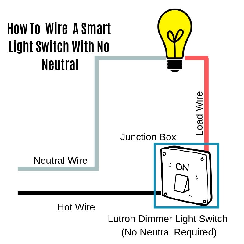
The universal dimmer is preset to the ledincandescent mode. The black wire power in source attaches to one of the switch screw terminals. Easily monitor control and optimize a lutron control system from any tablet pc or smartphone. Under most conditions the dimmer can be used with all compatible bulb types in this mode. Touch dimmer diagrams are for the following ranges v pro ir v pro multi point touch and remote and v pro eclique2. If you are replacing an existing 3 way switch.
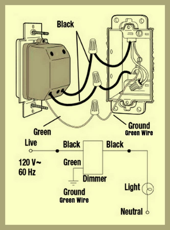
All metal faceplates must be earthed. The dimmer switch will have stranded wires that must be sliced to the solid cable wiring in a pigtail fashion. Switch on the mains supply and switch on the dimmer. Dimmer switches are not compatible with all fluorescent lights so be sure to always double check the dimmer switch is rated for the specific bulb you choose. Standard single pole dimmers and three way dimmers. With a standard single pole dimmer a single switch controls the.
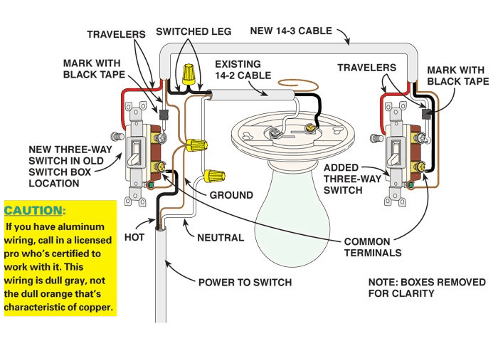
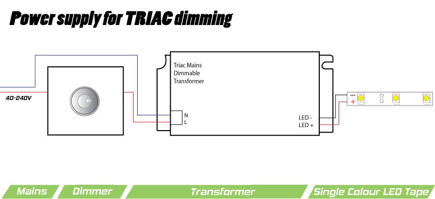
For multiple gangs repeat wiring where necessary. When replacing an existing 3 way switch take note of how the existing switch is wired before you remove the wiring then refer to your notes to help you wire the new 3 way dimmer switch. Dimmer switch wiring diagram. For dimming mlv fixtures the maximum lamp wattage is typically 70 85 of the transformers va rating. Dimmers come in two basic wiring configurations. A rheostat or dimmer makes it possible to vary the current flowing to a light fixture thereby varying the intensity of the light.
4 mount the dimmer and attach faceplate 5 turn power on at circuit breaker 2 load types and operation maestro cl pro dimmer ma pro 120 v 50 60 hz note. Switch wiring shows the power source power in starts at the switch box.

