When supply is provided the starter will interrupt the supply cycle of ac. What is use of choke in tubelight.

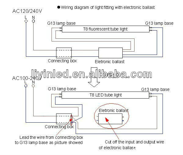
How To Install Electronic Ballast Or Electronic Choke
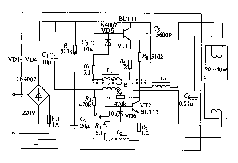
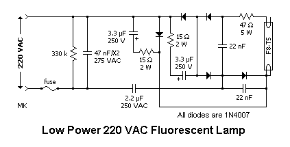
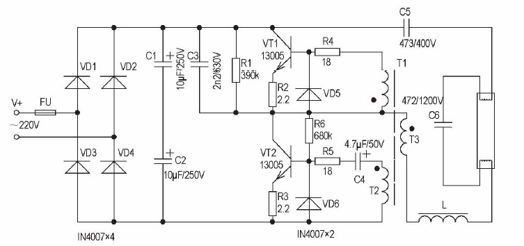
Tubelight electronic choke circuit diagram. Twin 40 watt ballast circuit diagram. This video is so important who are. The lower power factor circuit proven in figure 3 welcomes 115 vac or 230 vac 5060400 hz inputs to generate a moderate dc bus of 320 vdc. The tube light or fluorescent light is a low pressure mercury vapor gas discharge lamp and it uses fluorescent to produce white light. Electronics articles 8 aug 14. Circuit diagram for electronic choke tube light datasheet first line.
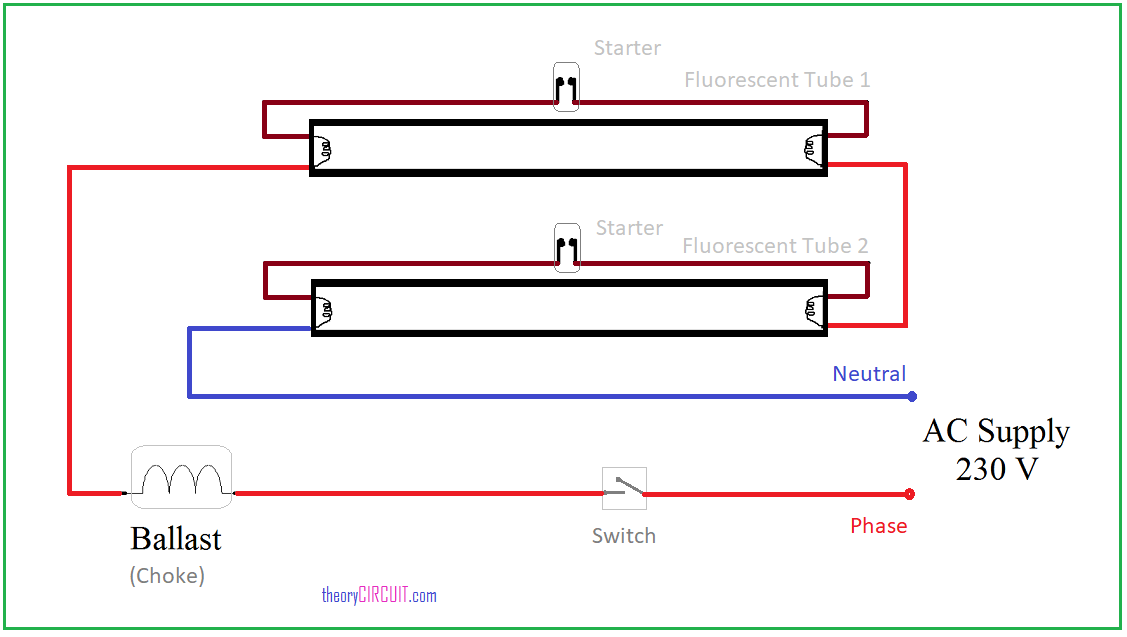
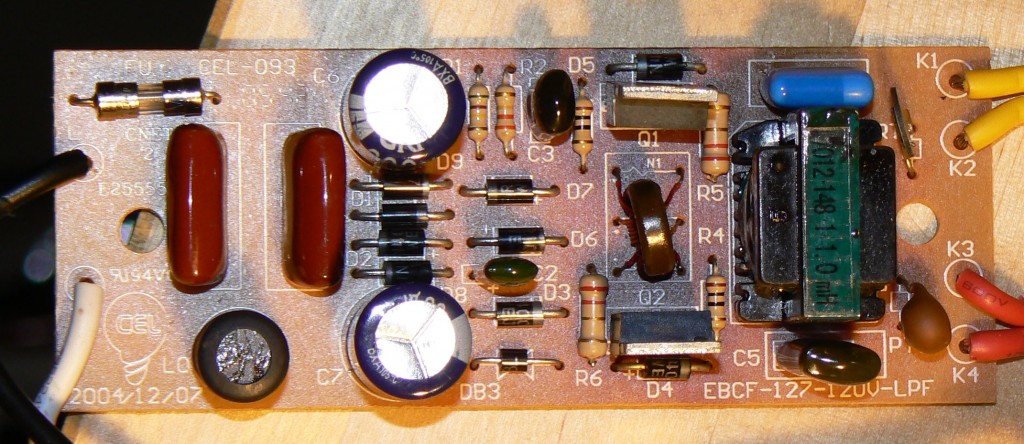
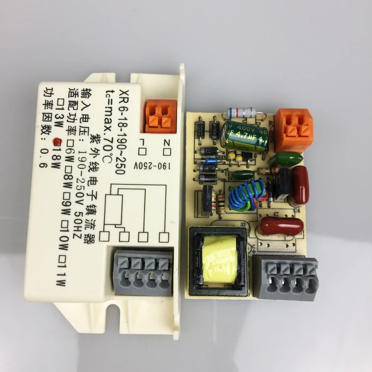
Tubelight electronic choke this circuit replaced the choke and starter in an existing frame. Cfl inverter circuit schematic diagram circuit diagram for electronic choke tube light cfl 12v inverter circuit schematic diagram free power 12v dc 220v 50w inverter 12vdc. One end of a starter is connected to pin 2 of terminal 1 and another end of the starter is connected to the pin 2 of terminal 2. This was an application note of mje13005 a high voltage switching npn power transistor. The function of choke is to provide high voltage enough for ionization to take place in a tube light and after establishment and substenance of ionization limit. One terminal of choke or ballast is connected to port 1 and another terminal is connected to pin 1 of terminal 1.
Tubelight electronic choke this is an electronic choke for a conventional fluorescent lamp. The diodes npn transistor and caps are high voltage 350v 1kv the tubelight is 40w 60w 5 feet long. Wiring diagram of single tube light installation with electronic ballast. The first is the minimal power factor circuit along with the other works with a novel diodecapacitor settings to accomplish a power factor 095. In this video i am going to show you how to connection 2 tubelight with electronic ballast. In electronics a choke is an inductor used to block higher frequency while passing direct current dc and lower frequencies of alternating current ac in an electrical circuita choke usually consists of a coil of insulated wire often wound on a magnetic core although some consist of a doughnut shaped bead of ferrite material strung on a wirethe chokes impedance increases with frequency.
I have explained so briefly so you can understand very easily. Tubelight circuit connection with diagram. A choke is connected in one end of the tube light and a starter is in series with the circuit. Connection of tube light is very simple because it has few wiring points only. Tube lights are most used light source and here tube light connection circuit and wiring diagram given with explanation. This circuit replaced the choke and starter in an existing.


