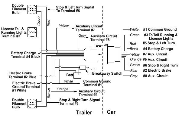
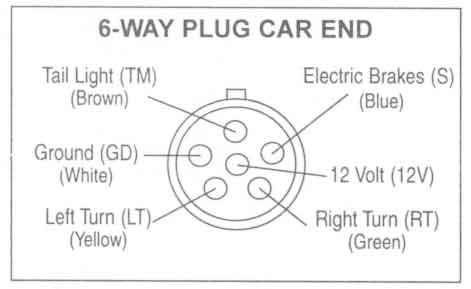
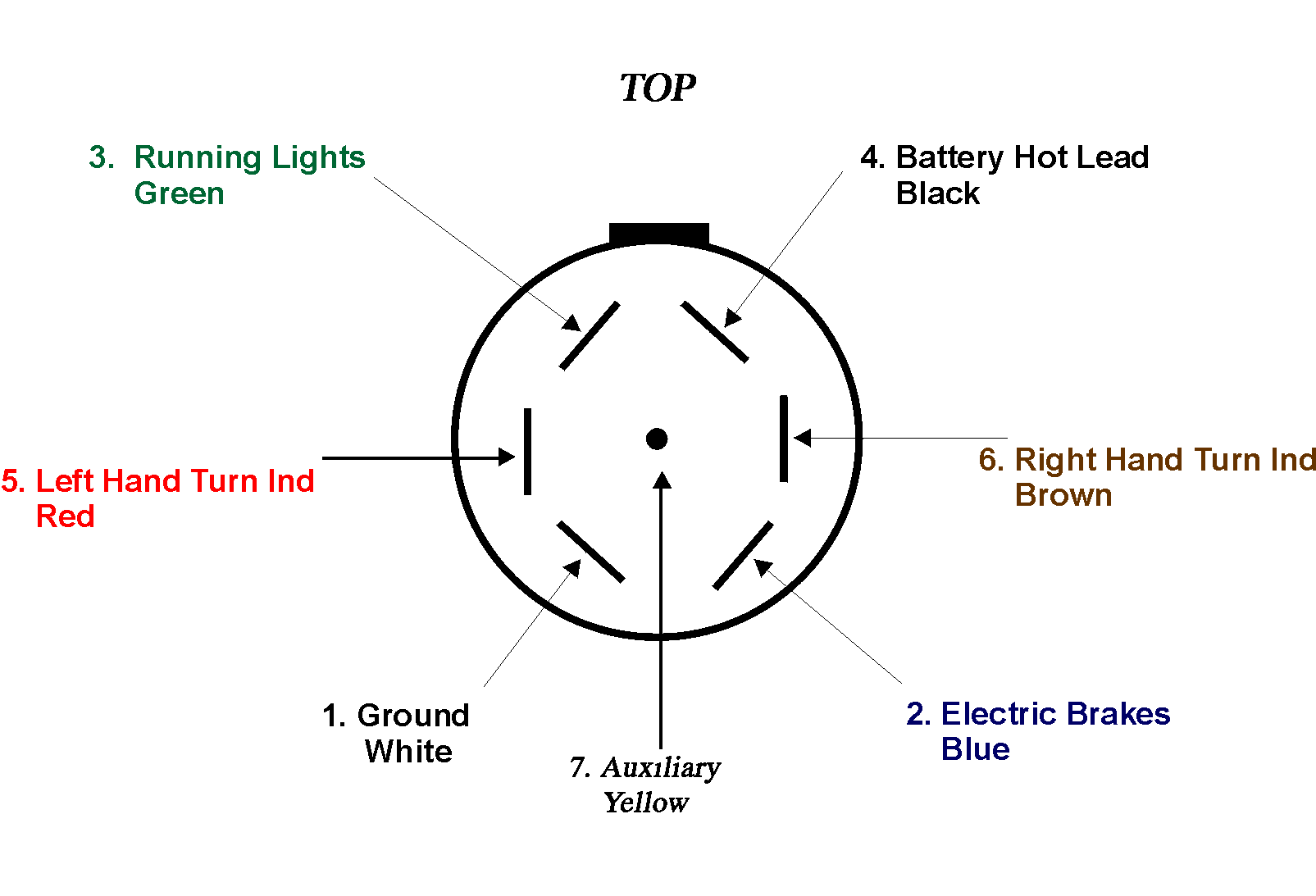
Trailer wiring diagram with electric brakes electric trailer jack wiring diagram collection bg for electric trailer brakes wiring diagram 10. Assortment of trailer wiring diagram with electric brakes.

1962 Cub Cadet Wiring Schematic C3 Wiring Diagram
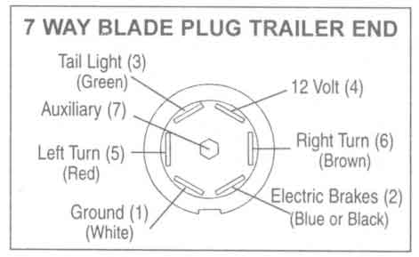
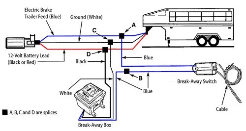
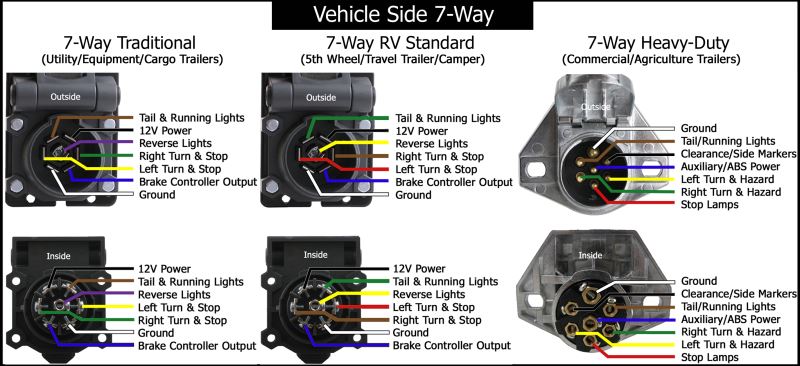
Trailer wiring schematic with electric brakes. 4 way trailer connectors are typically used on small trailers such as boat snowmobile utility and other trailers that that do not use brakes. A wiring diagram is a streamlined conventional pictorial representation of an electric circuit. If your trailer has 7 wires running all the way back to the brakes then yes you can tap into the existing wiring. Complete with a color coded trailer wiring diagram for each plug type this guide walks through various trailer wiring installation solution including custom wiring splice in wiring and replacement wiring. It reveals the parts of the circuit as streamlined forms as well as the power and signal connections in between the gadgets. Trailer wiring diagrams trailer wiring connectors.
Each component ought to be set and connected with different parts in particular manner. If your vehicle is not equipped with a working trailer wiring harness there are a number of different solutions to provide the perfect fit for your specific vehicle. Trailer wiring diagram with electric brakes 7 pin trailer wiring diagram with electric brakes 7 way trailer plug wiring diagram with electric brakes trailer light wiring diagram with electric brakes every electric arrangement is composed of various distinct pieces. The following trailer wiring diagrams and explanations are a cross between an electrical schematic and wiring on a trailer. Brakes probably need electricity too to actuate electric brakes or to disable hydraulic brakes when backing up. Trailer wiring diagrams trailer wiring connectors various connectors are available from four to seven pins that allow for the transfer of power for the lighting as well as auxiliary functions such as an electric trailer brake controller backup lights or a 12v power supply for a winch or interior trailer lights.
The four wires control the turn signals brake lights and taillights or running lights. If not the arrangement will not function as it ought to be. Assortment of electric trailer brake wiring schematic. One wire is for 12 volt power to the brake magnets and the other wire should be grounded either to the trailer frame or to the main trailer ground wire. Each of your new brakes will have two wires for the brake magnet. They also provide a wire for a ground connection.
4 way trailer connectors are. Various connectors are available from four to seven pins that allow for the transfer of power for the lighting as well as auxiliary functions such as an electric trailer brake controller backup lights or a 12v power supply for a winch or interior trailer lights. Each component should be set and connected with different parts in specific way. 7 pin trailer wiring diagram with brakes 7 pin flat trailer wiring diagram with brakes 7 pin rv trailer wiring diagram with brakes 7 pin trailer wiring diagram with brakes every electrical arrangement is made up of various different parts. As the name implies they use four wires to carry out the vital lighting functions.


