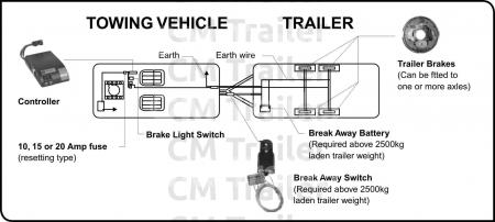
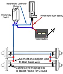
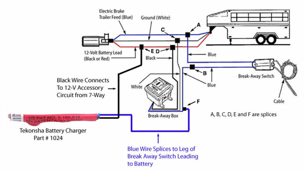
Splice one blue wire of the break away switch to the electric brake wire coming from the trailer side connector a see diagram on next page. They also provide a wire for a ground connection.

Cf 2094 Trailer Emergency Brake Wiring Diagram Schematic Wiring
Trailer emergency brake wiring diagram. You may have to cut into the trailer wirings sheathing to find the wire. Locate the trailer connectors blue wire that supplies power to the electric brakes. We recommend these standards because they are pretty universal. Trailer wiring diagrams trailer wiring connectors. See point c on the wiring diagram shown above. This car is designed not just to travel one place to another but also to take heavy loads.
Drill to secure to trailer. 4 way trailer connectors are typically used on small trailers such as boat snowmobile utility and other trailers that that do not use brakes. Splice or run the 12 volt hot lead black for tekonsha yellow for tow ready on the charger into the 12 volt hot lead running from the trailer connector to the trailer. Assortment of electric trailer brake wiring schematic. Next mount break away switch close enough on trailer that cable can be attached to vehicle. That said for specific situations there are industrial standards with different connectors and wire arrangements.
4 way trailer connectors are. Connect the breakaway switchs other lead to the blue wire with a scotchlok connector. See point d on the wiring diagram shown above. Trailer breakaway wiring diagram 3 wire trailer breakaway switch wiring diagram hopkins trailer breakaway wiring diagram rv trailer breakaway switch wiring diagram people today understand that trailer is a vehicle comprised of quite complicated mechanics. It reveals the parts of the circuit as streamlined forms as well as the power and signal connections in between the gadgets. Various connectors are available from four to seven pins that allow for the transfer of power for the lighting as well as auxiliary functions such as an electric trailer brake controller backup lights or a 12v power supply for a winch or interior trailer lights.
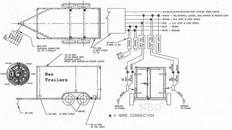
The following trailer wiring diagrams and explanations are a cross between an electrical schematic and wiring on a trailer. Wiring diagram for trailer breakaway switch save brake switch wiring 17 collection wiring diagram for brake controller unique trailer architectural wiring representations reveal the approximate locations and also affiliations of receptacles lighting as well as long term electrical solutions in a building. This connection will charge the battery when the vehicle is in use. A wiring diagram is a streamlined conventional pictorial representation of an electric circuit. As the name implies they use four wires to carry out the vital lighting functions. The four wires control the turn signals brake lights and taillights or running lights.


