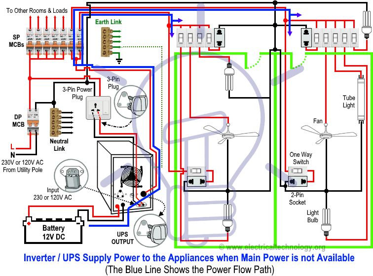
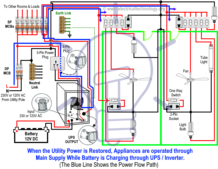
January 1 2016 at 625 am. Now according to the below ups connection diagram connect an extra wire phase to those appliances where we have already connected phase and neutral wires from power house db ie two wire as phase live as shown in the below fig.

Why 3 Phase Ac Instead Of Single Phase
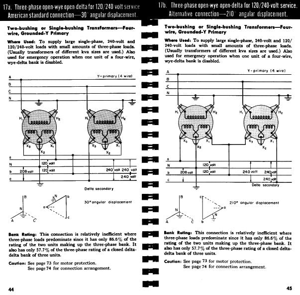
Three phase ups connection diagram. Similarly v bn leads v bn by 30º and v cn leads v cn by 30ºthis connection is also called 30º connection. The first step is to figure out the voltage of your phases. In three phase supply motors and large electric heaters can be directly connected to the three phases while in in single phase load light fan etc can be. If yes where from i may be get. These connections can be star or delta depending on the secondary of the distribution transformer. In the united states for low voltage motors below 600v you can expect either 230v or 460v.
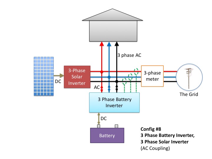
Three phase 3 line connection consist of three phase conductors and is employed only where there is no requirement for connecting phase to neutral loads. Preview the galaxy vx the newest 3 phase ups coming soon to north america. In the star connection three phase line to line phase to phase voltage are 415v ac in us 208v and single phase line to neutral phase to neutral there are 230v ac 120v in us. For more details on this innovative offer contact your sales representative. This video explains the basics of installing the eg3000 in a three phase distribution panel defines each incoming line. In the world of ups it is common to see refer to a single phase ups only by its kvakw rating ie.
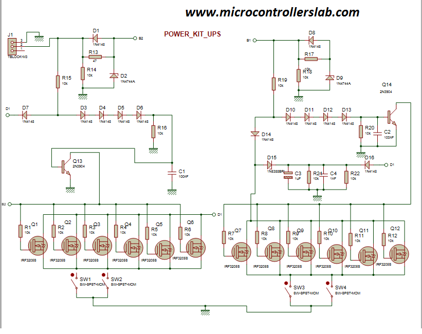
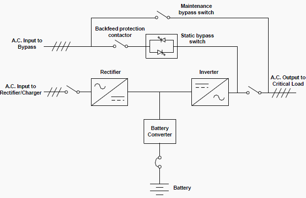
I want circuit diagram books of on line ups ranging from 1 kva to 30 kva single three phase of any different make models. Ups uninterruptible power supply circuit diagram in this article you will learn what is ups. However for a three phase ups it is common to refer to the kvakw rating along with the number of phases ie. Three phase systems can be three phase three wire or three phase four wire systems. A three phase square wave inverter is used in a ups circuit and a low cost solid state frequency charger circuit. Related electrical wiring tutorial.
Single phase may also be referred to as 1 phase or 1 phase and three phase as 3 phase or 3 phase. That being said there is a wide range of different motors and what you have on hand can be completely different. 20kva 31 or 100kva 33. Thus this is all about an overview of a three phase inverter working principle design or circuit diagram conduction modes and its applications. Ups inverter wiring diagram with auto manual changeover switch system. A three phase motor must be wired based on the diagram on the faceplate.
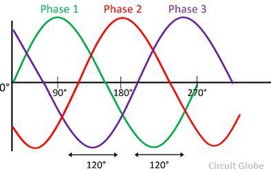
The phasor diagram of the y connection of the three phase transformer is shown in the figure below. Click here to learn more about. Three phase installation tutorial for the egauge eg3000 energy meter. A 3 phase inverter is used to convert a dc ip into an ac output. It is seen from the phasor diagram that the secondary phase voltage v an leads the primary phase voltage v an by 30.
