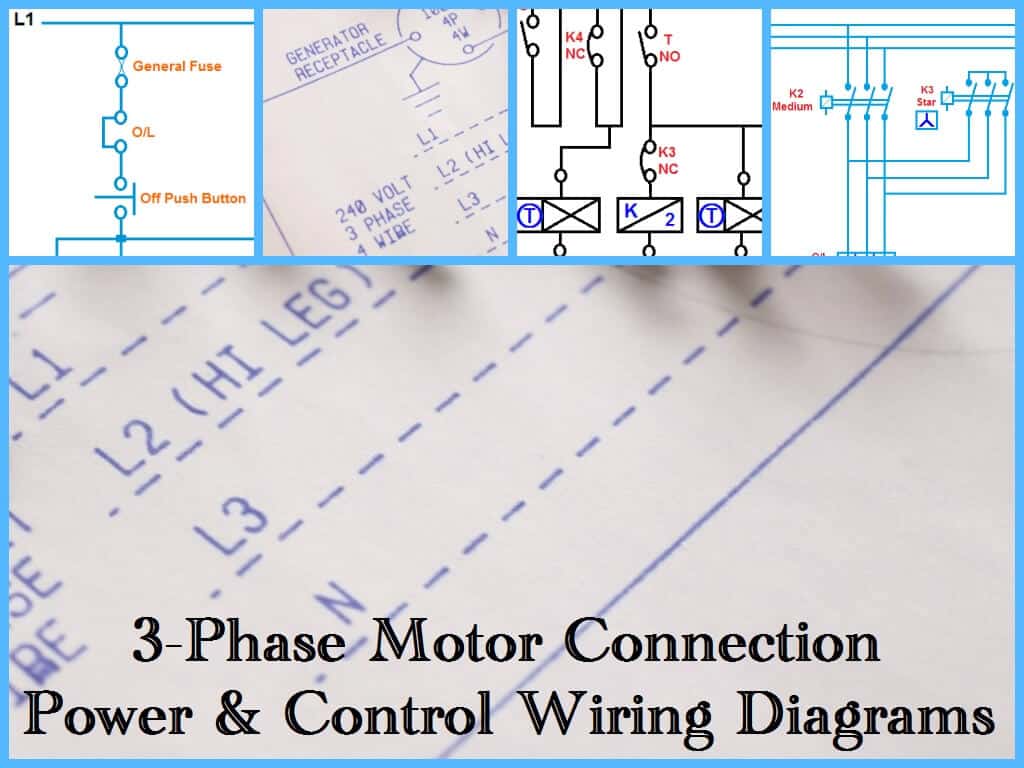
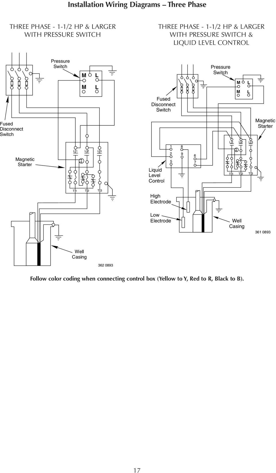
In which i control a three phase submersible pump motor using magnetic contactor. Collection of 3 wire submersible pump wiring diagram.
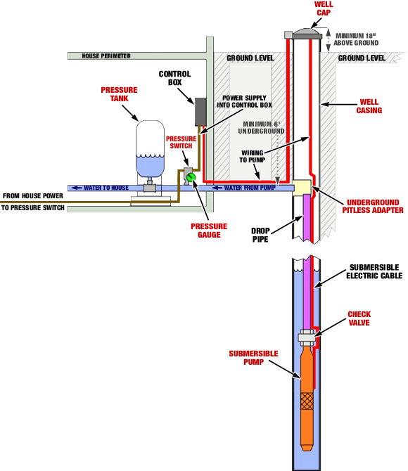
Pump Systems Lindsay Drilling
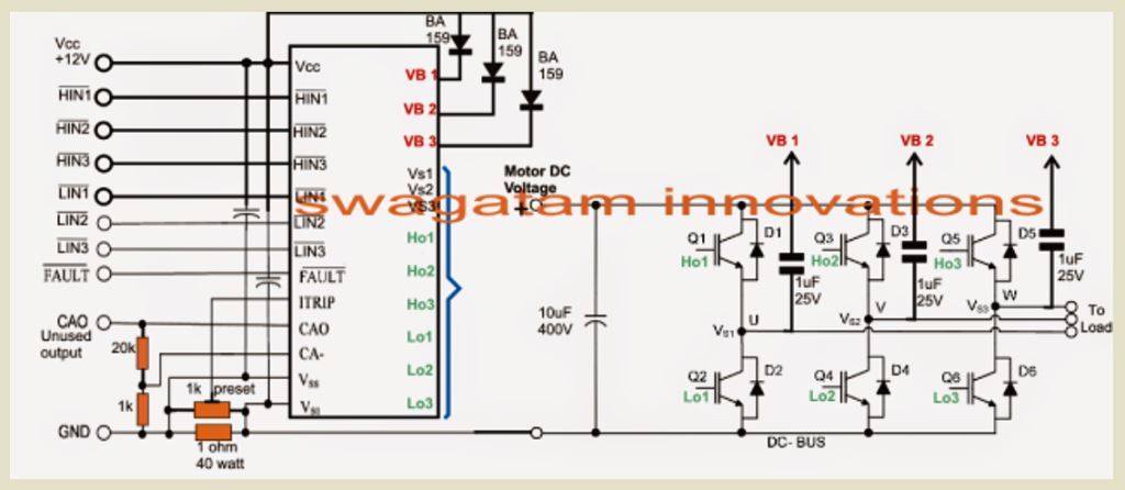
Three phase submersible pump wiring diagram. In this video i go over the differences of a 2 wire and a 3 wire submersible well pumpthis is associated with the starting components for the pump and whether they are located inside the motor. 3 phase submersible pump wiring diagram. Three phase submersible pump wiring diagram with straight star nonlinear starter. Volt or volt 60 hz single phase these 12 hp pumps come with a 15 electrical. A wiring diagram is a streamlined traditional photographic representation of an electrical circuit. In the above diagram i showed l1 l2 l3 and n wire incoming supplies with red yellow blue and black.
Jun 19 2017 single phase 3 wire submersible pump control box wiring diagram or single phase submersible pump starter wiring diagram and wiring installation guide. A submersible pump can be either two or three wire regardless of the voltage coming from the panel so start at your pump and follow the conduit back. If it runs straight to the pressure switch it is a two wire. Single phase wiring diagrams single phase wiring diagram for 05hp pumps with governor switch single phase wiring diagram with governor switch single phase wiring diagram without governor switch three phase wiring diagrams three phase 208v wiring diagram three phase 230v wiring diagram three phase 460v wiring diagram three phase 575v wiring diagram kb pump wiring diagrams kb pump 230v wiring. I hope after watching the above single phase submersible pump starter wiring diagram guide video tutorial i hope now you will fully understood the complete submersible pump control starter wiring diagram or installation and now you will be able to wire or make your own submersible pump motor starter however now if you have any question regarding the video tutorial or diagram then you can ask. Single phase submersible pump control box wiring diagram 3 wire submersible pump wiring diagram in submersible pump control box we use a capacitor a resit able thermal overload and dpst switch double pole single throw.
Here is the complete guide step by step. Submersible sump pumps by zoeller are great for pumping out the water in your steel handles and guards have automatic reset thermal overload protection can view 50 series pump performance curve chart view 50 series pump. Not only a contactor but also i install the thermal overload relay which will protect the motor form burning in case of over current flow to the circuit. It shows the elements of the circuit as simplified forms and also the power as well as signal links between the devices. First look at the 3 phase submersible pump wiring diagram and after that i explain each step below the connection diagram. The wiring connection of submersible pump control box is very simple.
If the conduit runs into a control box before continuing to the water pressure switch chances are you have a three wire pump.
