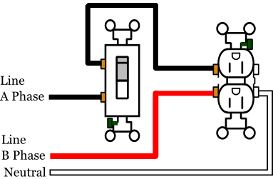
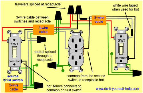
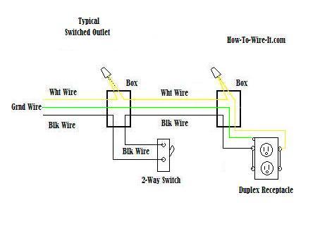
How to wire a switched outlet with a single pole switch is illustrated in this wiring diagram. Wiring a switched outlet wiring diagram.
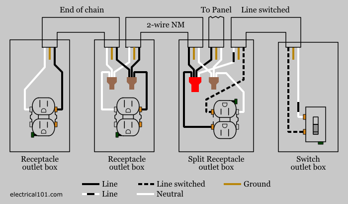
Split Recepticle Wiring Electrical 101
Switched outlet diagram. Before you shop for a new switch remove your old one from the boxafter making sure the power is off of courseand look for a neutral white wire. Wiring diagram for multiple switched outlets. Wiring a basic light switch. First locate the cable that is bringing power into the box. The basic 3 way switch wiring. Switched outlet diagram with hot and a neutral entering the switch box.
Wiring diagram for a switched gfci combo outlet. The process for removing the tab link from the outlet. The diagram below shows the power entering the circuit at the grounded outlet box location then sending power up to the switch and a switched leg back down to the outlet. From there a 3 conductor cable is installed to a switched electrical receptacle outlet. Take a closer look at a switched outlet wiring diagram. Wiring a gfci outlet with combo switch outlet receptacle light switch.
If that is the case pick the diagram that is most like the scenario you are in and see if you can wire your outlet. The source for the circuit is at the switch and 2 wire cable runs to each receptacle outlet. It means all the connected loads to the load terminals of gfci are protected. Before you install a new outlet check the code or. How to wire a switched outlet that gets its power from the switch box. In the wiring diagram above a hot and a neutral enter the single pole switch box.
This series of electrical wiring pictures shows how the actual wiring is attached using the top wiring diagram scenario 1 where the power enters at the switch box and a 3 wire romex runs from the switch box down to the grounded wall outlet. How to splice electrical wire the electrical tape is optional. Notice that these outlets have the tab removed from the hot side or brass side of the outlet which allows the top half of the plug to be controlled only from the switch. The source neutral is connected the line neutral terminal. Click on image for larger. Home about us.
You may want to have a plug that has a lamp plugged in and is operated by a switch while keeping the other outlet hot. At the outlets each is wired using a pigtail splice to make the hot and neutral connections. The source hot wire is spliced with one of the switch wires and the other switch wire is connected to the hot line terminal on the device. A two conductor cable is installed from the switched outlet to feed an outlet that is live at all times. This diagram shows the wiring for multiple switched outlets on one switch. This is a problem if your old switch is wired as a switch loop such that only a hot and a switched hot are available in the box.
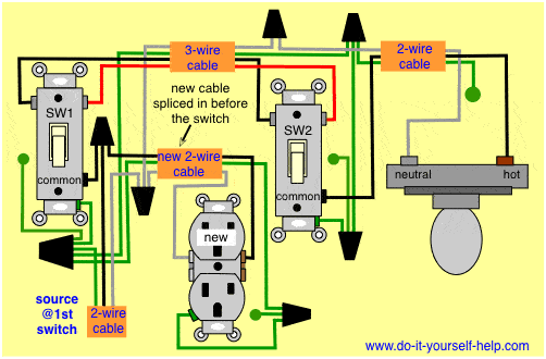
You will see at least one 2 wire cable and the added. Switched outlet wiring diagram. Diagram for a half hot switched outlet that gets power in the outlet box the preferred method. Wiring a light switch wiring diagram. In this gfci outlet wiring and installation diagram the combo switch outlet spst single way switch and ordinary outlet is connected to the load side of gfci. Single pole switch to an outlet.
In this diagram the switch built into the combo device is wired to control the gfci outlet itself.


