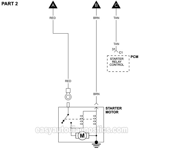
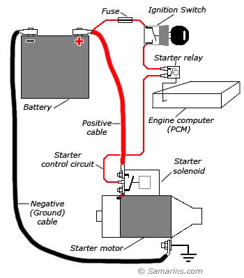
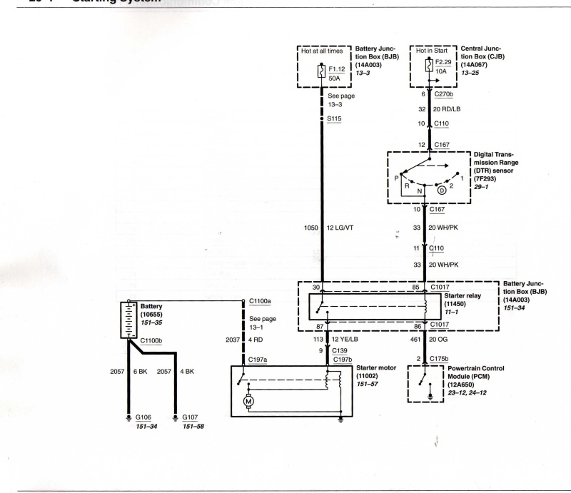
Ac compressor clutch relay. The above typical starter motor circuit wiring diagram applies only to the 1990 25l sohc dodge dakota.
Gp1800 Wiring Diagram Errors Yamaha Factory Service Manual
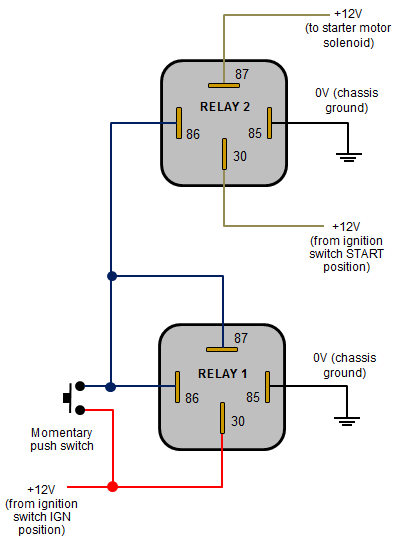
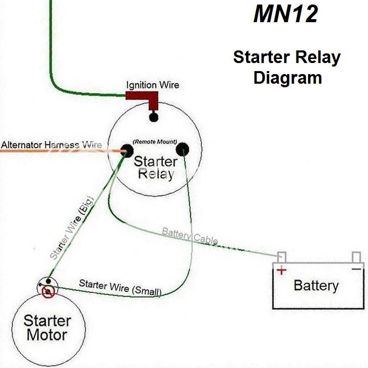
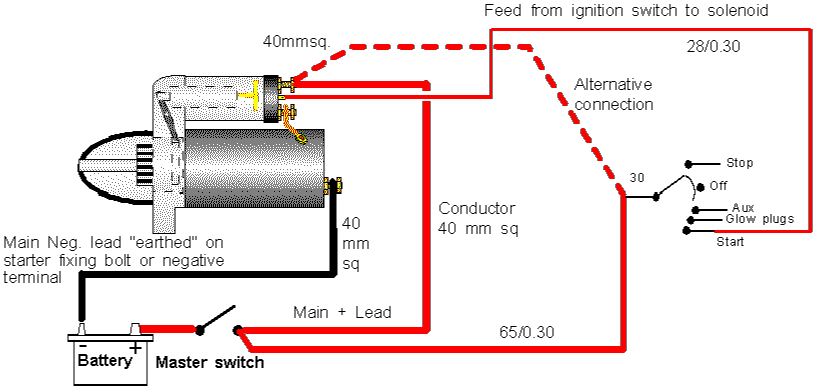
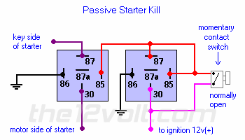
Starter motor relay diagram. If one of these components fails you nissan will not start. The motor starter must have at least two components to operate. The basic starter kill relay diagram shown below breaks continuity of the wire from the ignition switch to the starter motor or in some cases ie. Heated rear window relay. This allows a minimal 12 volt signal from the ignition switch to activate a magnetic. Windscreen wiper motor relay 2onoff 8.
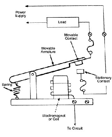
See how the anti. Other devices for disconnecting and short circuit protection may be needed typically a circuit breaker or fuses. Engine coolant blower motor relay 1. 5 152 engine coolant heater valve relay rear heater 6 38 acheater recirculation flap relay. Windscreen wiper motor relay 1 lowhigh wiper speed 7. A relays purpose is to interpose between the ignition switch and the powerful current hungry starting motor.
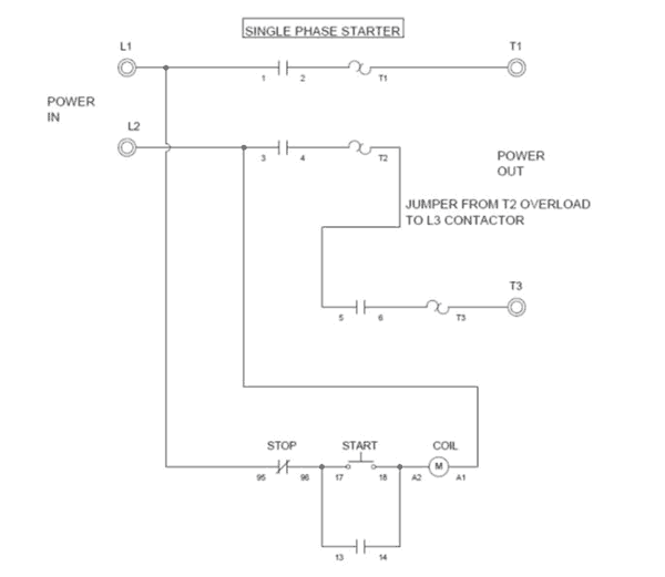
Starter motor relay location 1990 25l dodge dakota the starter motor relay is located in the engine compartment on the driver. Heaterac blower motor relay. Engine coolant blower. A contactor to open or close the flow of energy to the motor and an overload relay to protect the motor against thermal overload. Fortunately you can isolate and troubleshoot each component to quickly determine which component is causing your nissan not to start properly. Before the engine starts the alternator does not generate electricity the voltage of the neutral tap n binding post is zero no current passes through the charge light relay starter relay coil and charging indicator relay contacts are.
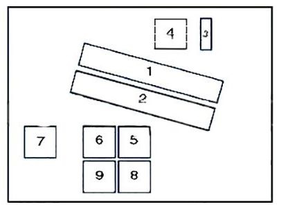
The starter system in a nissan consists of the battery ignition relay switch starter motor and starter solenoid. Radiator fan starter motor relay and engine coolant temperature sensor. 7 53 alternator relay aes with 150aalternator 8 53 alternator relay acvauf with 150a alternatoratatc 9 175 starter motor inhibitor switch relay. Engine coolant blower motor relay2. Learn to navigate this systems wiring circuitry and diagram using current flow analysis relay and module operation and neutral switch actuation such as circuit completion. In this article we consider the third generation ford focus before facelift produced from 2012 to 2014.
The security starter relay controlled car starter wiring diagram is as shown in the following picture. This is the most commonly used application for disabling the starter. Starter relays have appeared in various forms since the first electric starter motors were installed in automobiles. 53 heater blower relay rear warm air 4 114 heater blower relay atc. Ford to another relay when the alarm is armed and the ignition is turned on. It includes the following circuits.
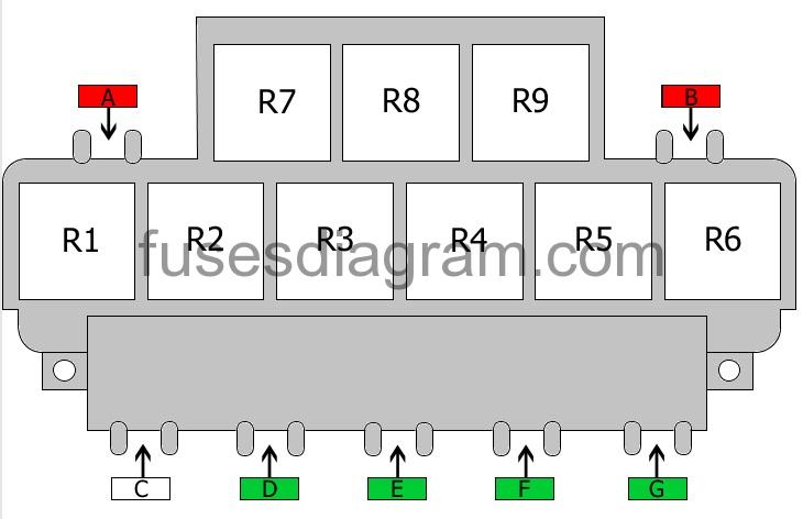
Here you will find fuse box diagrams of ford focus 2012 2013 and 2014 get information about the location of the fuse panels inside the car and learn about the assignment of each fuse fuse layout and relay.
