It shows the components of the circuit as streamlined forms as well as the power and also signal links in between the tools. 3 phase isolation transformer wiring diagram sample 3 phase circuit breaker wiring diagram beautiful 2 pole circuit.
Onboard Isolation Transformer Vs Safety Page 3 Cruisers
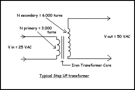
Single phase isolation transformer wiring diagram. Single phase transformers like other electrical devices may be connected into series or parallel arrangements. Transformer wiring diagram isolation changing doorbell 4 wire. Isolation transformer wiring diagram collections of 3 phase isolation transformer wiring diagram sample. 45 kva transformer wiring diagram sample. The maximum value of the magnetic flux density is 11t when 2200 volts 50hz is applied to the transformer primary winding. Transformer basics example no3.
The connection diagram on the left shows how a deltadelta connection can be made either with three single phase transformers or with one three phase transformer. For example distribution transformers are normally wound with the secondary or low voltage windings that can be connected in series or parallel. Variety of 3 phase isolation transformer wiring diagram. V l is the line to line voltage and v p is the phase to neutral voltage. To make the transformer connections compatible with three phase supplies we need to connect them together in a particular way to form a three phase transformer configuration. A collection circuit is a circuit in which elements are linked along a single course so the current circulations with one element to.
Here is a good explanation about it in this video. The placement of these dots next to the ends of the primary and secondary windings informs us that the instantaneous voltage polarity seen across the primary winding will be the same across the secondary winding. To ensure compatibility check the wiring diagram by clicking a part number and viewing its product page. Single phase isolation transformer selection guide. A single phase transformer has 480 turns on the primary winding and 90 turns on the secondary winding. All the transformers in this section are rated for both 50 and 60 hz for use worldwide.
The maximum flux in the core. A transformer can not act as a phase changing device and change single phase into three phase or three phase into single phase. To test the accuracy of the transformer voltage we take a 3000 va single phase 220v iuput to 110v. A wiring diagram is a simplified standard pictorial depiction of an electrical circuit. Need more detail of ato isolation transformer. Electrical transformer wiring diagram new isolated ground.
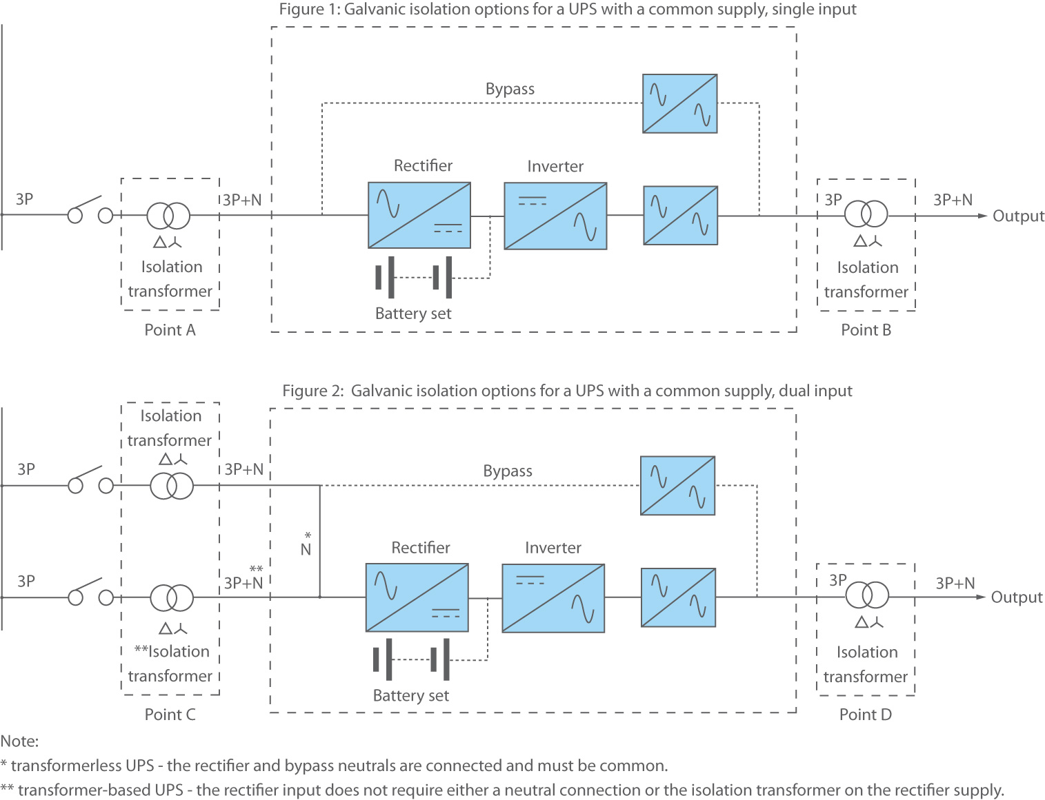
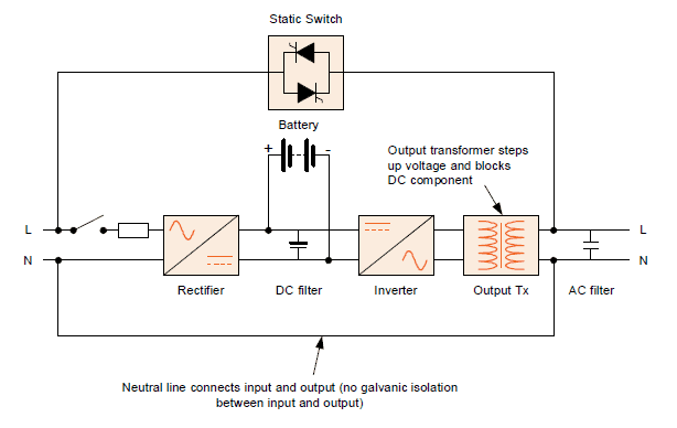
Typically a single phase transformer wiring schematic has a dot on both the primary and secondary windings. The dashed lines indicate the transformer outlines. Funky square d transformer wiring diagram image best for. Ac why does a ups need an isolation transformer electrical.


