In the above one phase motor wiring i first connect a 2 pole circuit breaker and after that i connect the supply to motor starter and then i do cont actor coil wiring with normally close push button switch and normally open push button switch and in last i do connection between capacitor. Terminal markings and internal wiring diagrams single phase and polyphase motors meeting nema standards b.

Three Phase Wikipedia
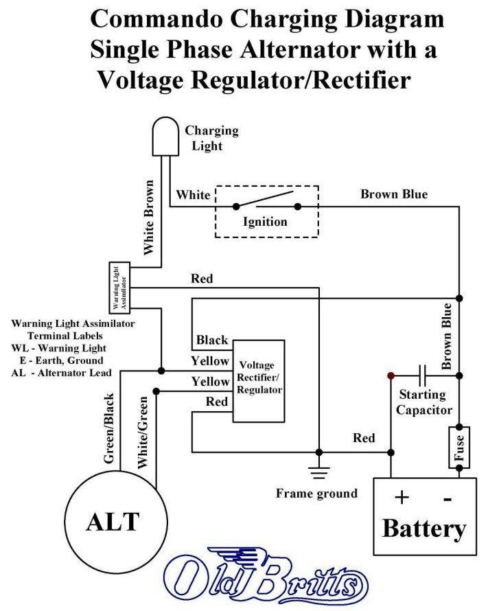
Single phase alternator wiring diagram. Operation principle of brushless alternator in all alternators voltage may be generated by rotating a coil wire in the magnetic field or by rotating a magnetic field within a stationary coil wire it doesnt matter whether the coil is moving or the magnetic field is moving. A generator that produces a single continuously alternating voltage is known as a single phase alternator. All of the alternators that have been discussed so far fit this definition. Single phase generators can be used to generate power in single phase electric power systems. Modern lucas alternators are made on brand new equipment to the original drawings. The stator armature windings are connected in series.
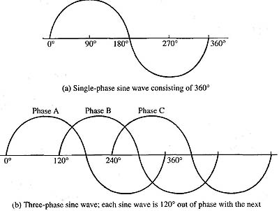
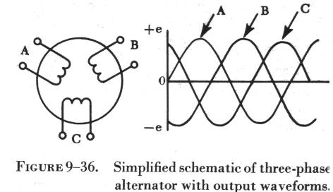
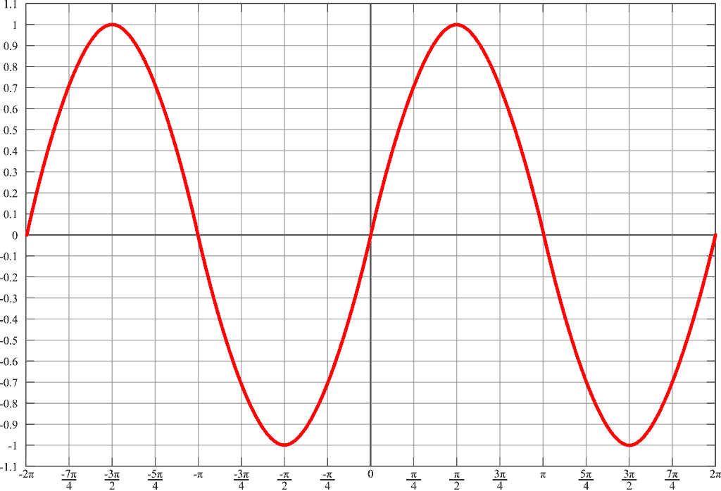
The individual voltages therefore add to produce a single phase ac voltage. However polyphase generators are generally used to deliver power in three phase distribution system and the current is converted to. Single phase generator also known as single phase alternator is an alternating current electrical generator that produces a single continuously alternating voltage. Internal connections may be changed to provide for 230 or 115vacrms at either 50hz or 60hz. U n w w2 w6 v6 w1 v2 w5 u1 u2 u5 u6 v1 v v 240v 12 lead double delta available voltages 10 lead generators are not reconnectable as double delta generators connected as zig zag should be reconnected as double delta. Conversion between nominal voltages and frequencies is a matter of changing contacts on a terminal strip inside the terminal box.
Single phase reversing contactor wiring diagram. In single phase supply 230v in uk eu and 120v in us canada there are 2 one is line live and the other one is neutral incoming cables from the utility poles to energy meter and then directly connected to the main distribution board consumer unit. If a single phase motor is single voltage or if either winding is intended for only one voltage the terminal marking shall be determined as follows. Single phase wiring installation is the most common wiring in residential buildings. Ring and use the correct size rotor the wiring will need to be modified as the rm12 had 6 wires. In a single phase ac generator the armature conductors are connected in series so as to form a single circuit which generates a single phase alternating emf and hence it is called single phase alternator.
Single phase systems are the cheapest option whilst 3 phase systems give much better output at low rpms. When driven at constant rotational speed they generate single phase current at constant ac voltage and frequency. Single phase ac generator. Why 3 phase ac instead of single phase. Double delta connections always provide 240120v single phase t3. The simplified version of a ac generator is discussed here.


