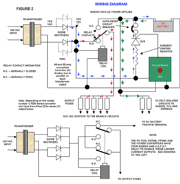
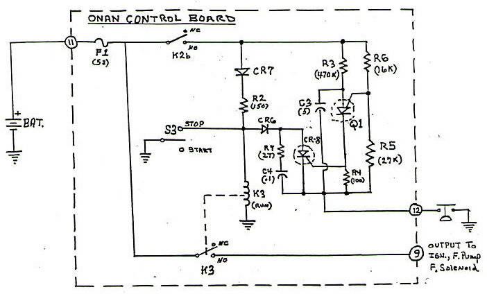
Asco 7000 series automatic transfer switch wiring diagram beautiful. Asco automatic transfer switch series 300 wiring diagram collections of asco automatic transfer switch series 300 wiring diagram collection.

Wiring Diagram For 3 Way Switch With 4 Lights Light Switch
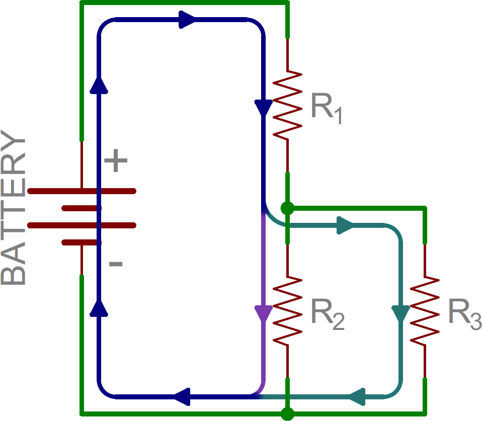
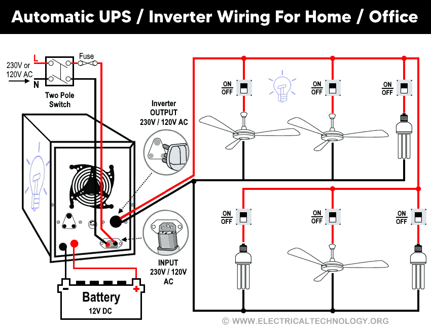
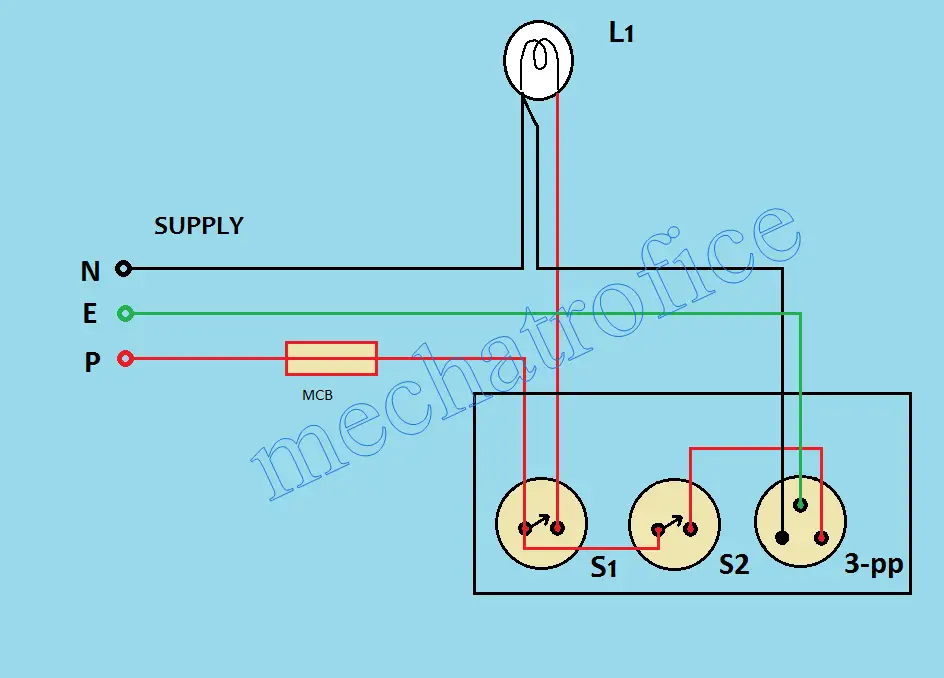
Series board wiring diagram. Lg tv circuit diagram i will share some lg tv circuit diagram here. Here you can see there is a cut in the line wire connected to lamp 3 so the bulb is switch off and the rest circuit is working. The following explanation will help you understand better how to design home wiring layouts. Asco series 300 wiring diagram sources. How to wire a switch and a load a light bulb to an electrical supply. Asco automatic transfer switch series 300 wiring diagram collection.
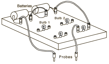
We can test the condactor by using this board. So we are sharing the diagram of this all circuits. Most popular lg tv circuit is lg cf20f schematic lg cb775bn tv set lg pc 53a. Lg tv is a most popular brand tv in many country. Designing home wiring layouts. The uses and advantage of series testing board in unlimited and we can use it for many thing.
As can be seen in the diagram the wiring is pretty simplethe phase is invariably applied to one terminal of the switch the other terminal moves to one of the connections of the load and the other. Another major defect of series lighting circuit is that as all lamps or bulbs are connected between line l and neutral n accordingly if one of the light bulb gets faulty the rest of the circuit will not work as the circuit will be open as shown in fig below. A wiring diagram is a simple visual representation of the physical connections and physical layout of an electrical system or circuit. This is simple diagram of series board but we can not test low resistance appliances electrical devices however my incoming post will be about the series board for low resistance appliances testing. When some one searching for lg tv circuit diagram just ask me in comments i will try to. It shows how the electrical wires are interconnected and can also show where fixtures and components may be connected to the system.


