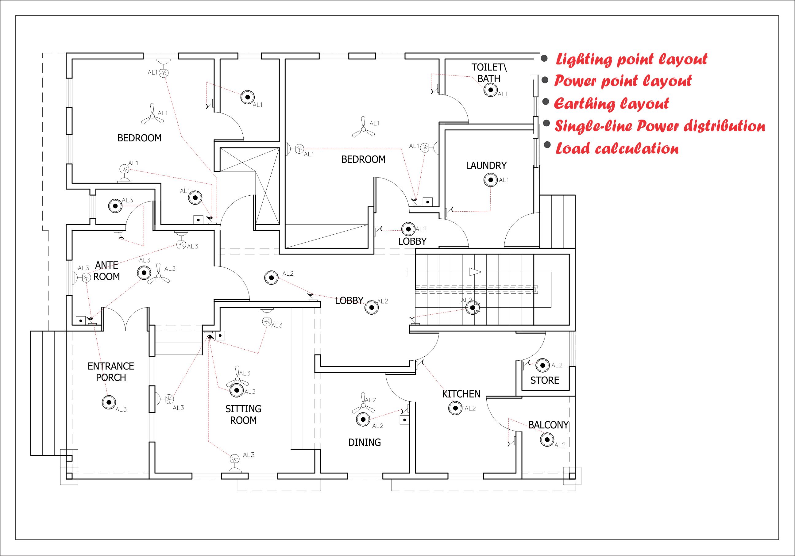
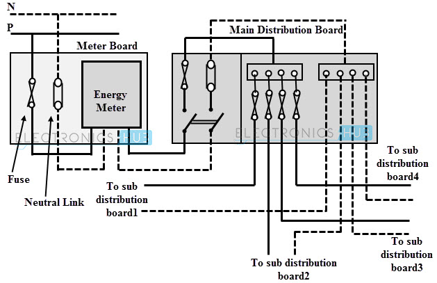
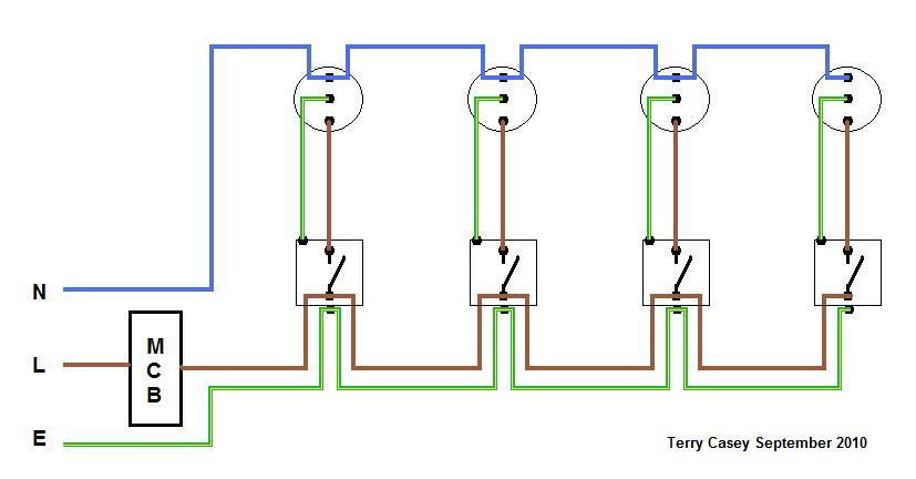
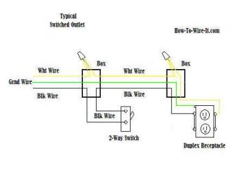
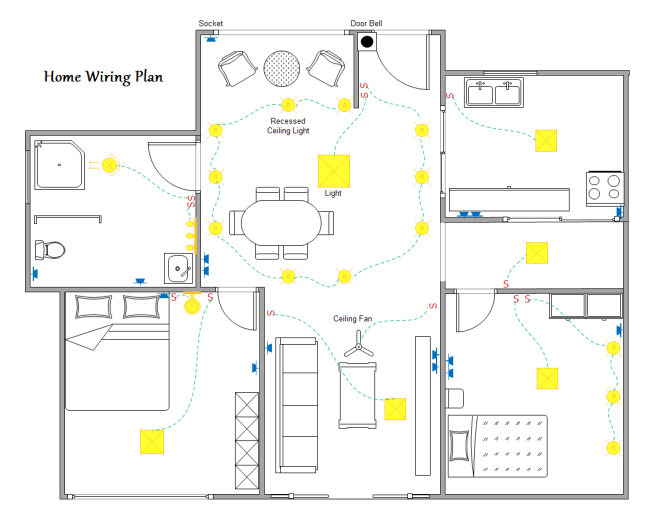
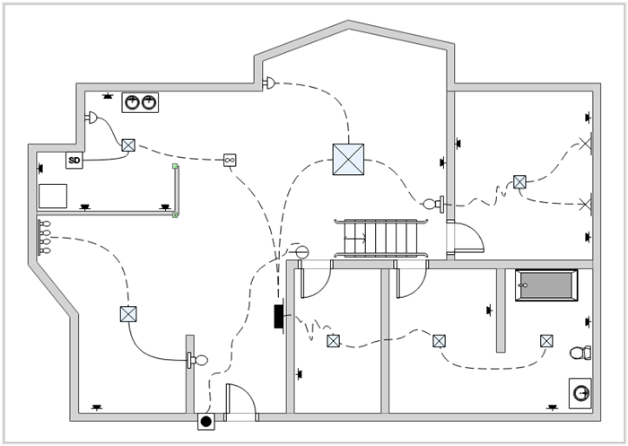
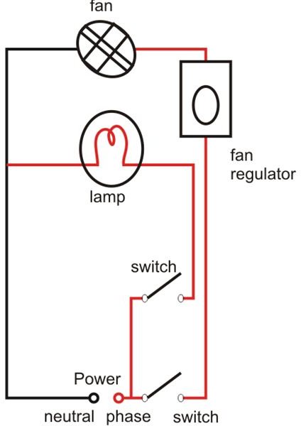
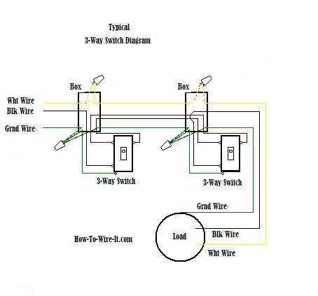
They are crucial to the assembly of the circuit or system. Wiring diagrams or layouts illustrate the physical connections or wiring between components.

Building Simple Resistor Circuits Series And Parallel
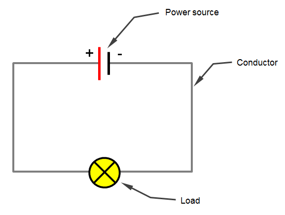
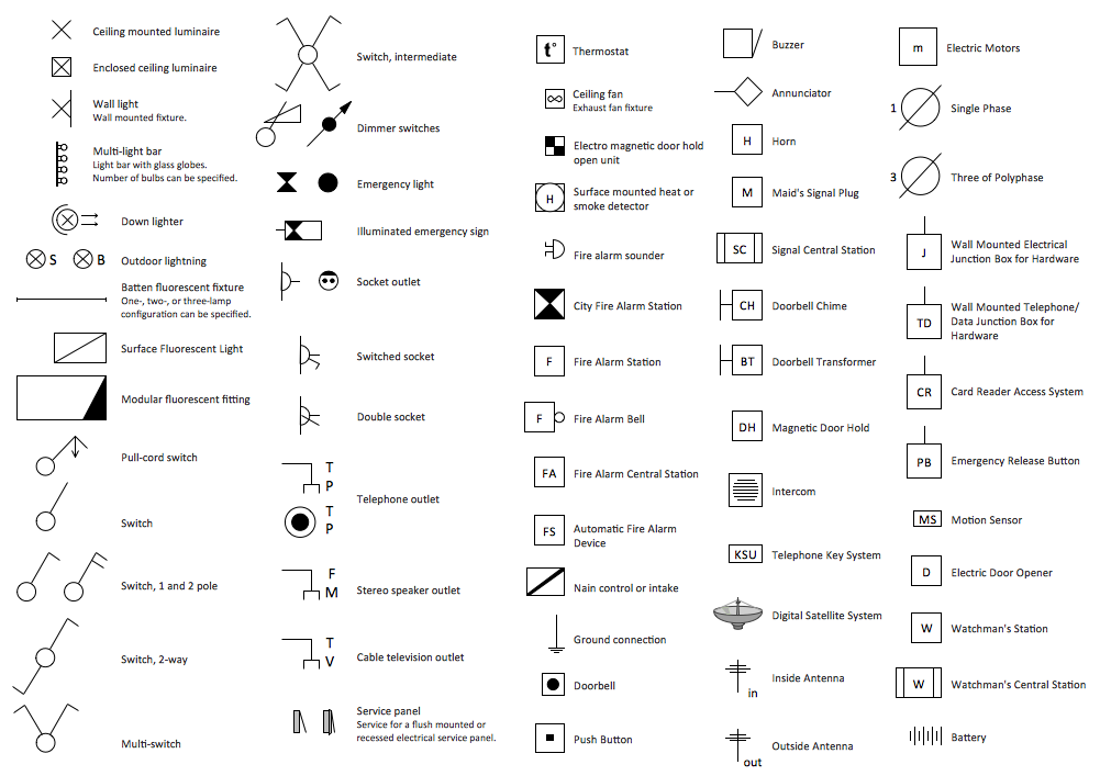
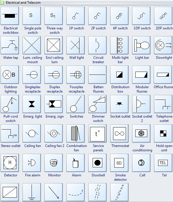
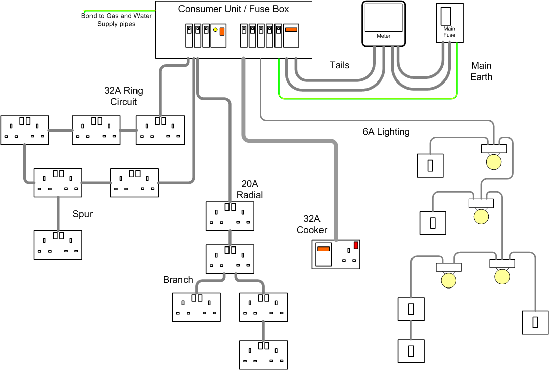
Schematic diagram of building wiring. It makes the process of building circuit easier. Symbols that represent the components in the circuit and lines that represent the connections between them. A wiring diagram is a type of schematic that uses abstract pictorial symbols to show all the interconnections of components in a system. A schematic diagram is a picture that represents the components of a process device or other object using abstract often standardized symbols and lines. Series and parallel circuits building circuits in series or parallel requires a good understanding of schematics. Working with wire or skip the breadboard and jump straight into wiring stuff up.
Hvac control systems and building automation system electrical intended for building management system schematic diagram image size 882 x 663 px and to view image details please click the image. Wiring diagrams show how the wires are connected and where they should located in the actual device as well as the physical connections between all the components. Knowing how to cut strip and connect wire is an important electronics skill. Unlike wiring diagram it does not specify the real location of the components the line between the components does not represent real distance between them. The diagram offers visual representation of the electric structure. 2004 polaris sportsman 90 wiring diagram wiring diagram is a simplified within acceptable limits pictorial representation of an electrical circuitit shows the components of the circuit as simplified shapes and the power and signal friends amongst the devices.
A schematic is defined as a picture that shows something in a simple way using symbols. Parts that are shown broken down into their sub components for the schematic retain their complete package format for the wiring diagram. Crownline wiring diagram schematic diagram sea ray boat wiring diagram. The schematic diagram of an electrical circuit shows the complete electrical connections between components using their symbols and lines. Wiring schematic diagram by facybulka posted on june 2 2019 series and parallel circuits building circuits in series or parallel requires a good understanding of schematics. How does this diagram aid with circuit building.
Schematic diagrams only depict the significant components of a system though some details in the diagram may also be exaggerated or introduced to. Here is a picture gallery about building management system schematic diagram complete with the description of the image please find the image you need. Wiring diagrams are made up of two things. How is a wiring diagram different from a schematic. On the other hand this diagram is a simplified version of the arrangement. A schematic shows the plan and function for an electrical circuit but is not concerned with the physical layout of the wires.

