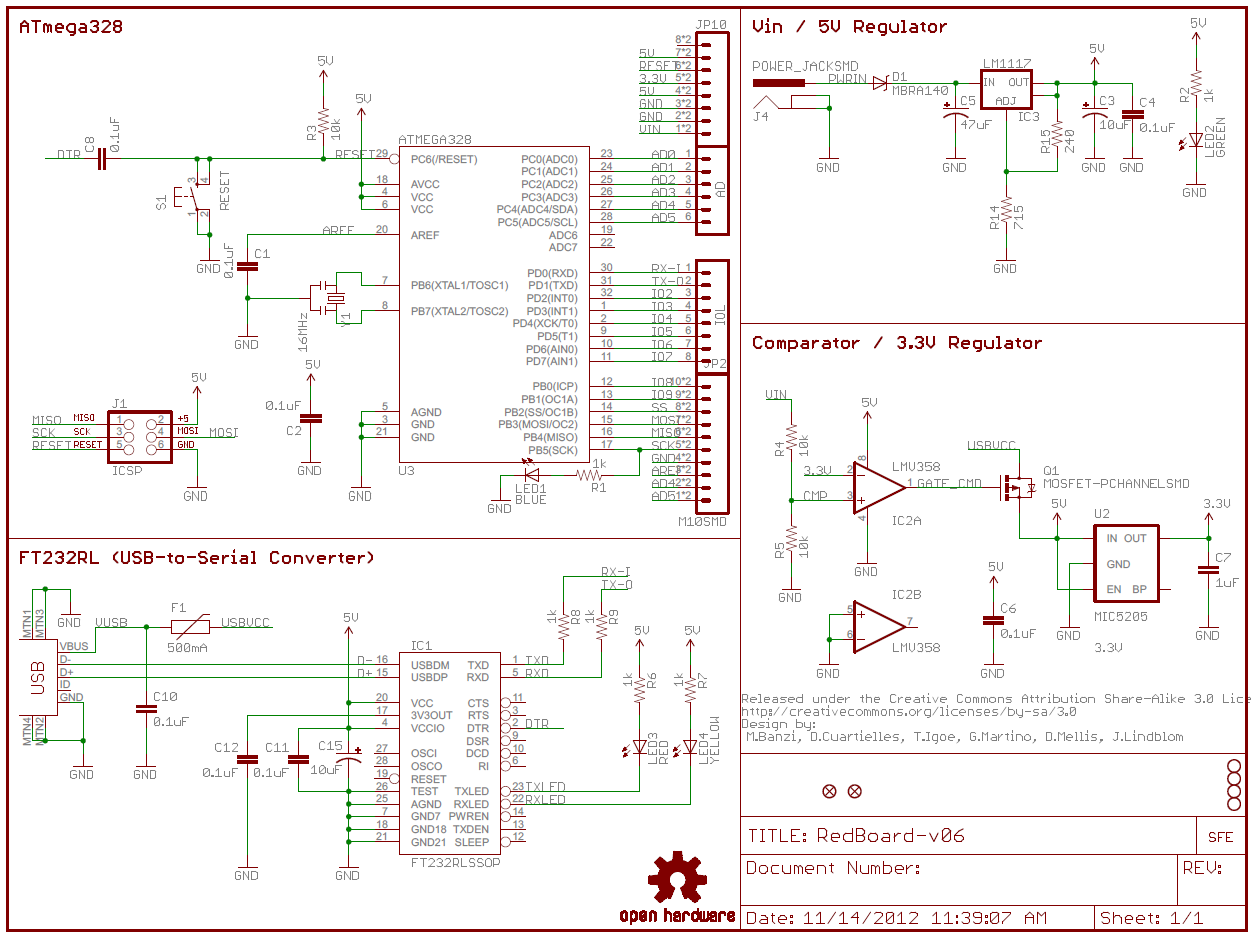
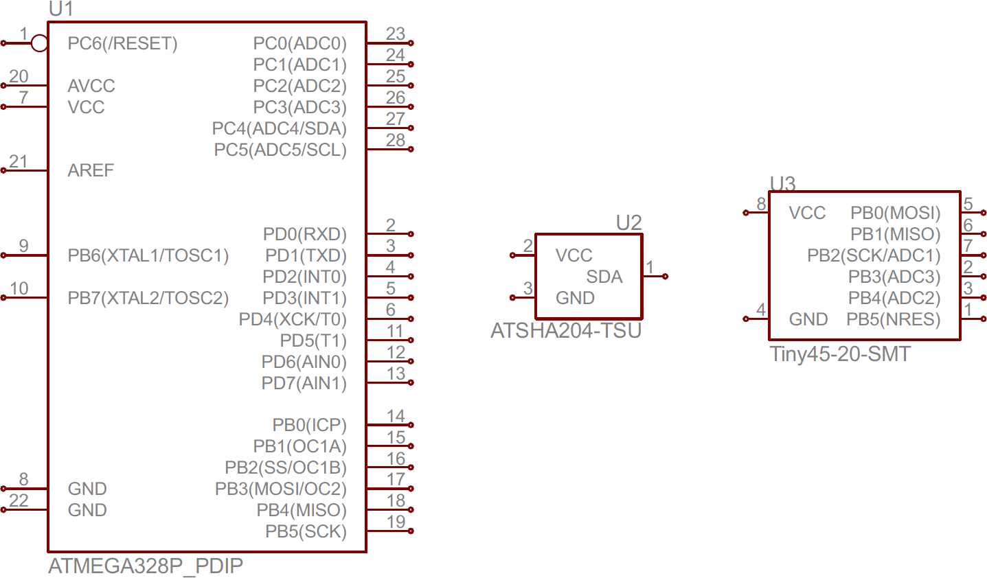
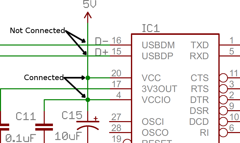
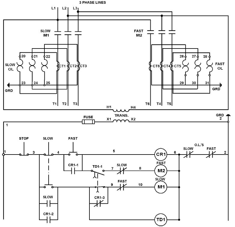
Circuit or schematic diagrams consist of symbols representing physical components and lines representing wires or electrical. Understanding how to read and follow schematics is an important skill for any electronics engineer.

6948 Images Of Reading Electrical Wiring Diagrams Wire
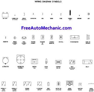
Read electrical diagram. Familiarize with standardized electrical symbols knowing the meanings of basic electrical symbols in your electrical drawing will help you quickly understand and troubleshooting the circuit. Well go over all of the fundamental schematic symbols. Learn to read electrical and electronic circuit diagrams or schematics. Schematics are our map to designing building and troubleshooting circuits. Then well talk about how those symbols are connected on the schematics. To read a wiring diagram first you have to know what fundamental elements are included in a wiring diagram and which pictorial symbols are used to represent them.
To read electrical schematics the fundamental electrical schematic symbols should be understood. How to read a electrical drawing 1. A first look at a circuit diagram may be confusing but if you can read a subway map you can read schematics. A lamp is usually represented as a circle with a cross inside it. Especially if you start messing around with building little electronics projects. For all the electronics hobbyist wannabes this is a must read instructable.
The purpose is the same. The common elements in a wiring diagram are ground power supply wire and connection output devices switches resistors logic gate lights etc. At first glance an electrical schematic may come across as a confusing cluster of multicoloured lines and symbols of various shapes and sizes which can be true however they are much more than that. This tutorial should turn you into a fully literate schematic reader. Knowing how to read circuits is a very useful skill that will help you out all the time. In this article i will help you to learn how to read and understand an electrical schematic.
Recognizing electrical schematic symbols here are some of the standard and baisc symbols for various components for electrical schematics. In the process i understood components and a little bit about circuitry. If you know what to look for itll become second nature. Getting from point a to point b. A drawing of an electrical or electronic circuit is known as a circuit diagram but can also be called a schematic diagram or just schematic. This instructable will show you exactly how to read all those confusing circuit diagrams and then how to assemble the circuits on a breadboard.
When the current passes through the lamp it will produce light. Literally a circuit is the path that allows electricity to flow. The best way to read and understand electric circuit diagrams is to read in conjunction with actual circuit construction. When i was a teenager i bought electronics kits from a local hobby store and built hundreds of small electronic projects.
