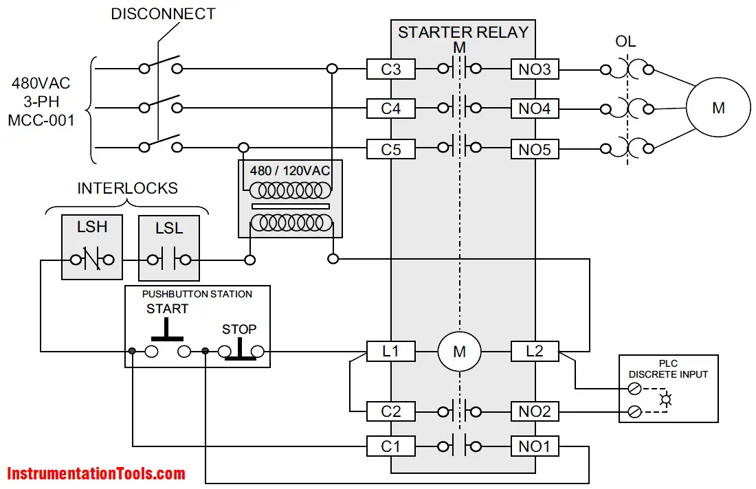
But it does tend to become more complex. These look like a normally closed nc contact.

Guide To Safety Relays And Safety Circuits
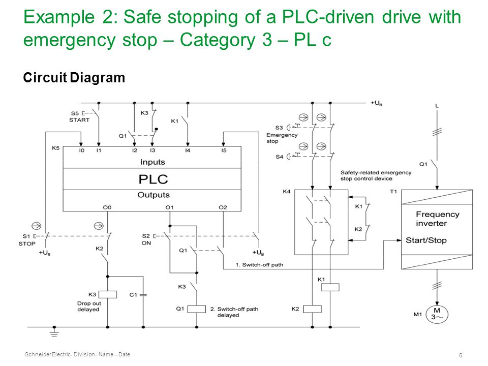
Safety plc wiring diagram. What is a safety plc. All critical safety functions should be hardwired this way. Just like on the diagram we start with the stop push button. A safety relay is in other words a well tried components and thats why you should use to build your safety system. It shows the elements of the circuit as streamlined shapes as well as the power as well as signal connections in between the tools. Lets try to explain it in a simple way for non experts.
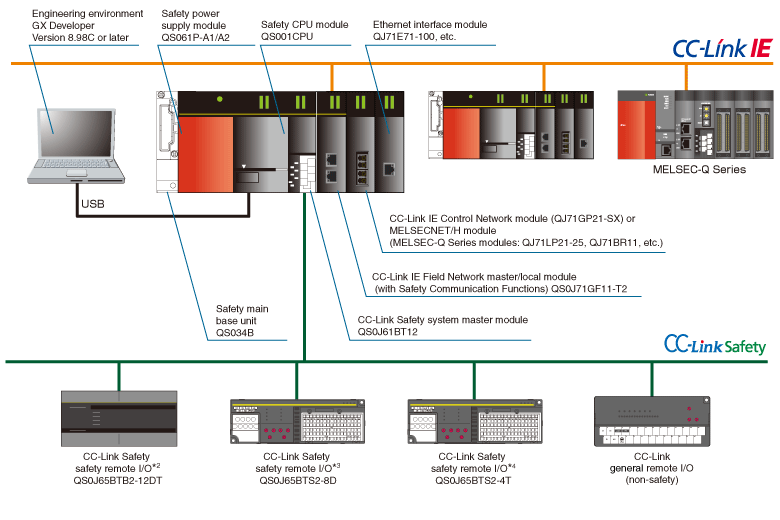
So when you are building an automation system or a machine you cannot use a plc for the safety related parts of the machine. It will be represented with an examine off bit. Figure 5 below shows a schematic diagram for a plc based motor control system similar to the previous motor control example. The fundamental difference with a general purpose plc is summed up in one word diagnosisin addition there are differences in terms of internal architecture software and firmware and certification for applications where compliance with a certain sil level is required. A wiring diagram is a simplified conventional photographic representation of an electric circuit. Im using the siemens tia portal as the plc programming software.
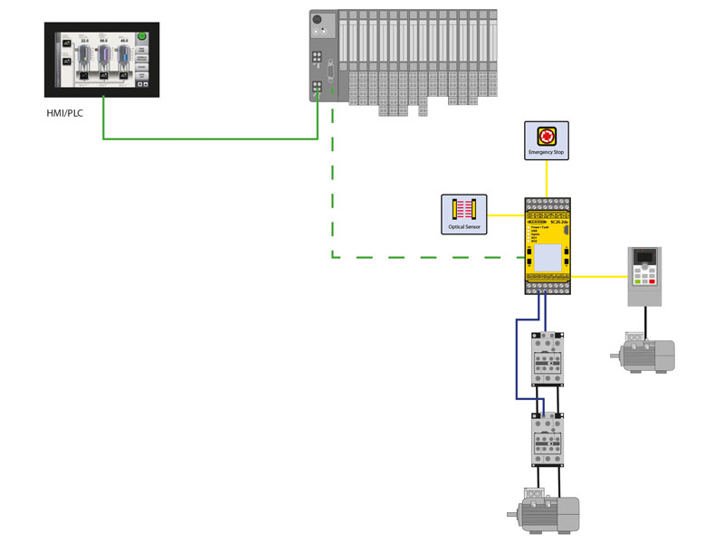
Assortment of plc panel wiring diagram pdf. Lets start converting our simple wiring diagram to the plc program in a step by step format. This figure shows the e stop wired to cutoff power to all of the devices in the circuit including the plc. On the other hand a plc for example is not a well tried component.


