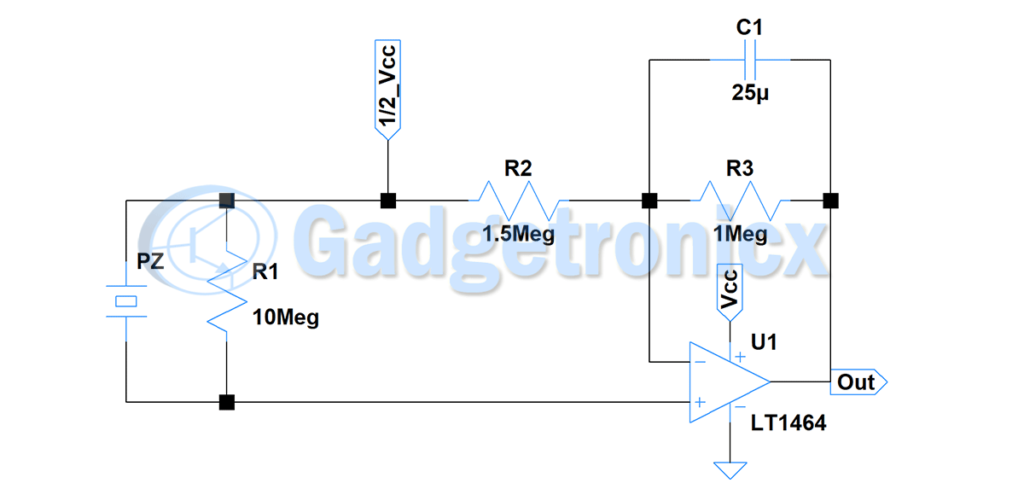
In order to calibrate the above circuit measure the output voltage from voltage divider made up of fsr and r1 after you apply pressure on fsr which you intend to fix as a trigger point for your circuit. Each part ought to be set and linked to other parts in specific way.
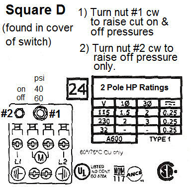
Square D 40 60 Pump Pressure Switch
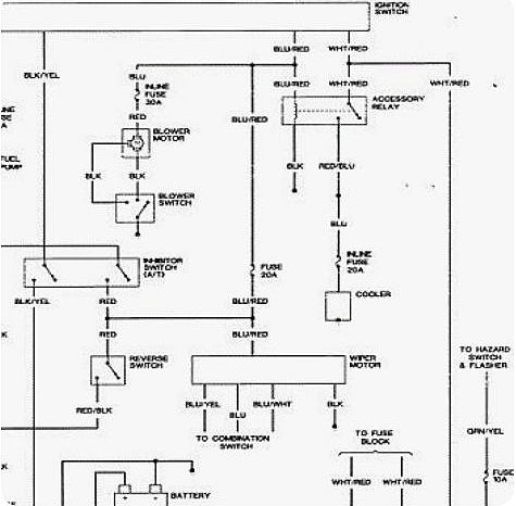
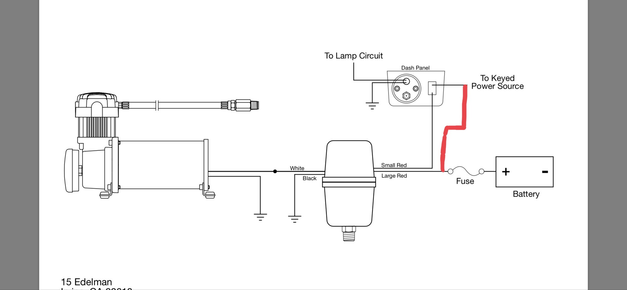
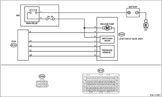
Pressure switch circuit diagram. A wiring diagram is a streamlined standard photographic representation of an electric circuit. Collection of well pump pressure switch wiring diagram. Washer for sealing 2. The micro switch is used to make or break an electrical circuit when the pressure switch operates. Without the use of the switch the water pump would always be on or off. Oil pressure switch wiring diagram alco oil pressure switch wiring diagram danfoss oil pressure switch wiring diagram engine oil pressure switch wiring diagram every electrical arrangement is made up of various distinct parts.
A simple pressure switch with a range of 50 to 350 bar can be made using a pressure sensor. Collection of well pump pressure switch wiring diagram. This switch is made up of one normally close contact nc and one normally open contactno. Switch contacts a normally open b normally closed 6. If not the arrangement will not function as it ought to be. Now set the voltage output of divider r2 and r3 little lower than the above voltage.
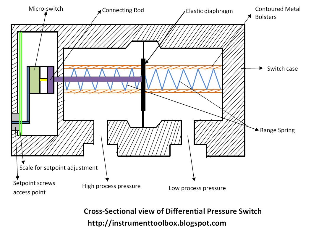
If you can accept somewhat reduced linearity the sensor can even be used up to 500 bar. Variety of water pump pressure switch wiring diagram. The micro switch in the sectional view is a single pole double throw spdt switch. A wiring diagram is a streamlined standard photographic depiction of an electric circuit. Pressure switches are used on water pumps for the accurate control of the pump as it produces pressurized water. So a shorted sensor will render the crank sensor inoperable.
Engine oil pressure switch. However with the pressure switch the pump can be adjusted to turn on and off at predetermined settings to control the pump and subsequent pressure. Well pump pressure switch wiring diagram collection. A wiring diagram is a simplified traditional. As shown in the schematic diagram the circuit contains very few components other than the sensor. Calibrating the pressure switch circuit.
It so happens that on some vehicles cadillacs the high pressure sensor is connected to the other sensor voltage reference line. Posted on march 31 2018 august 9 2018 by headcontrolsystem. Pressure switch circuit diagram beautiful sump pump float adjustment.


