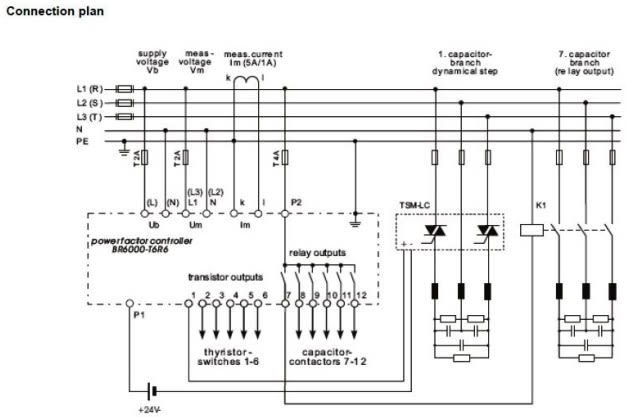
Three phase motor connection stardelta without timer power control diagrams. In order to measure electrical power the relay needs to receive the line voltage and current from a current transformer ct installed close to the metering point if possible.

Ca 9146 Ac Capacitor Wiring Diagram Bank
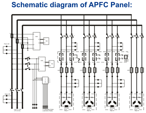
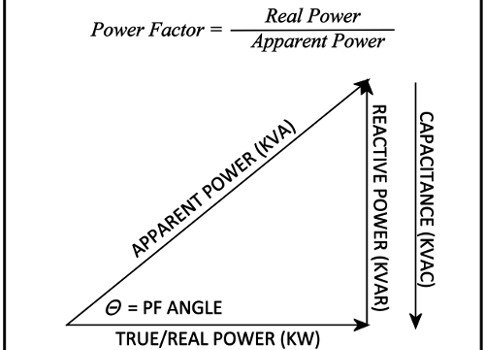
Power factor panel wiring diagram. Star delta y δ 3 phase motor starting method by automatic star delta starter with timer. Pf measures how effectively the current is being converted into useful work output and indicates the effect of the load current on the efficiency of the supply system. Note that apfc panel can maintain the power factor on lt side of transformer and it is necessary to provide fix compensation for power transformer refer fig no 1 5. In electrical engineering the power factor of an ac electrical power system is defined as the ratio of the real power absorbed by the load to the apparent power flowing in the circuit and is a dimensionless number in the closed interval of 1 to 1. Power factor correction is the method to reduce the lagging power factor in inductive loads by fixing a high value capacitor across the phase and neutral close to the load. Apfc stands for auto power factor correction panel.
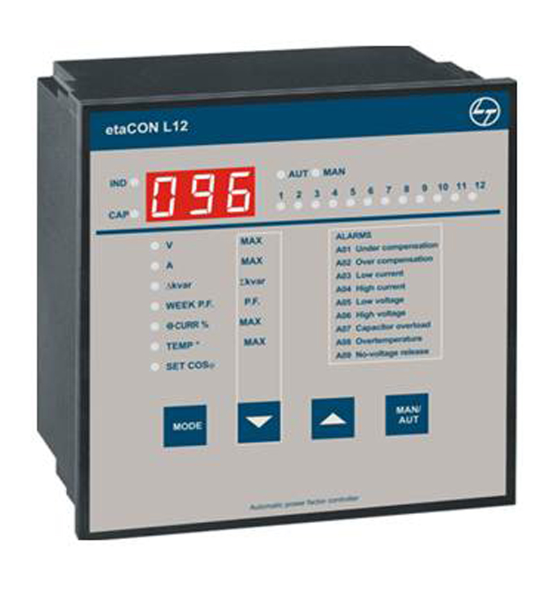
Do not oversize power factor correction capacitorsdo not connect kvar units to the load side of a starter or contactor for motors subject to reversing plugging or frequent starts. In case there is no transformer in the installation then the ct for sensing power factor should be provided at the incoming of main switch of the plant. Automatic power factor controller 12 power factor power factor pf is the ratio of active power p to apparent power s expressed as wva. In this video you will see how to wire power factor relay and power capacitors to create a complete power factor correction panel. It is used to improve power factor to meet the current requirement to reduce the billing and also to improve feeder voltage regulation. A power factor of less than one indicates the voltage and current are not in phase reducing the average product of the two.
Crane or elevator motors or any motor where the load may drive the motor or multispeed motors or motors involving open transition reduced voltage starting. To measure reactive power at the power factor relay especially it must be ensured that the vectors of voltage and current are shifted by 90. When the voltage and current are in phase with each other in an ac circuit the energy from the source is fully converted into another form to drive the load and in this. Psif we can get to 200 likes i will make another. Three phase motor connection schematic power and control wiring installation diagrams. Circuit diagram of pf relay.


