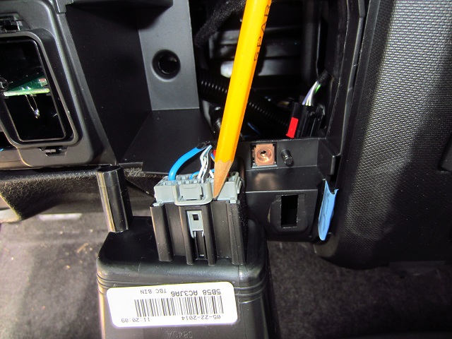
A wiring diagram is a simplified traditional photographic depiction of an electrical circuit. Wiring harness dkblue trailer brake controller switched outputred fused trailer brake controller battery feedblack brake controller groundlt blue vehicle stop lamp switch to brake controller input brown brake controller illuminationcontroller wires red white blue and blackplease let me know what wires go where.

Wo 6510 Reese 7 Pin Wiring Diagram Free Diagram
Pod brake controller wiring diagram. These time actuated controls have solid state electronics and can be mounted in any position horizontal vertical even turned upside down. Collection of prodigy brake controller wiring diagram. This vehicle is designed not just to travel one location to another but also to carry heavy loads. Purchase a wiring harness specific to your vehicle application from your vehicles manufacturer and plug that harness into the recommended connection portal. Reese has always strived to provide the right trailer towing system for each application. It shows the elements of the circuit as simplified forms as well as the power and also signal connections between the devices.
Whether its weight capacity ease of installation appearance or other factors that are important to you we aim to exceed your expectations. Timed brake controls are great choices for your basic economical light duty towing needs. Connect the supplied pigtail wiring harness into the electrical connection port on the rear of the pod brake controller. Reese trailer brake controller wiring diagram hayman reese trailer brake controller wiring diagram reese electric brake controller wiring diagram reese pilot trailer brake controller wiring diagram people today comprehend that trailer is a vehicle comprised of very complicated mechanisms. This is why we offer as many as ten different trailer hitches for a single vehicle.


