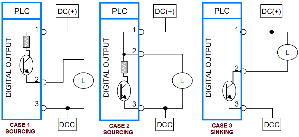
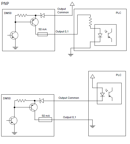
Digital output do circuits. Shows which direction power flows through the circuit.
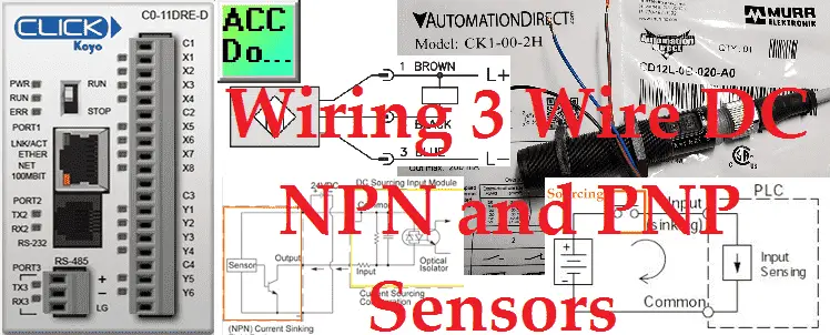
Plc Input Wiring Diagram Acc Automation
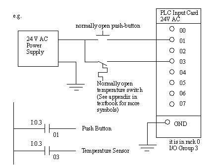
Plc digital output wiring diagram. Plc digital outputs can be thought of as relay contacts. Remove and lock out input power from the controller and io before any plc installation and wiring begins. The picture to the right shows an example of what the wiring of a plc with 4 inputs would look like. Software a software based plc requires a computer with an interface card but allows the plc to be connected to sensors and other plcs across a network. The cable diagram connection to the plc digital output port pluggable connector is illustrated in the. How to follow an electrical panel wiring diagram duration.
Note that these diagrams are without a barrier or isolator fuses and surge protector for keeping it very simple and understandable. The following are ten recommended procedures for io wiring. Digital input card in plc. In many cases that is just what they are. Verify that all modules are in the correct slots. How to wire the output to a relay or an indicator light.
The supply for the signal. The optocoupler input terminal block modules convert the ac signals to the proper dc levels to the plc. In others the switching element may be a solid state device of some sort. Check module type and model number by inspection and on the io wiring diagram. Output is an output of your ace plc. This might seem odd since we only had 2 wires so far.
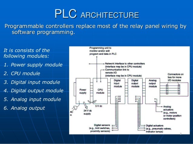
Most analog outputs on plcs works very much like a 3 wire transmitter. Figure 31 typical configurations for plc 32 inputs and outputs. A cable supplied with each terminal block module is then connected to the ace digital input port. Current analog output wiring. In order to increase io points on plcs without increasing the number of connections commons are used. Plc wiring 32 quantities of io and limited abilities but costs will be the lowest.
Everything inside the dashed box happens inside the plc. ˇ ˇ ˇ dl405 system ˇ ac power load supply input supply powering io circuits using separate supplies. The aces digital output ports can be connected to a relay terminal block module through a short standard cable supplied with the module. Wiring 1768 l43 inputoutput cards duration. In this article we are sharing the basic concepts of plc and dcs control systems wiring diagrams for digital input di digital output do analog input ai and analog output ao signals. For digital inputs that are ac signals the aces digital input ports can be connected to velocio optocoupled input terminal block modules.
Relay contacts are considered output devices because they force other devices to react when they change state. But the plc often provides an internal power supply giving us the third wire. The example wiring diagram below on the right shows how this can work but also that the auxiliary supply output is an unused resource.
