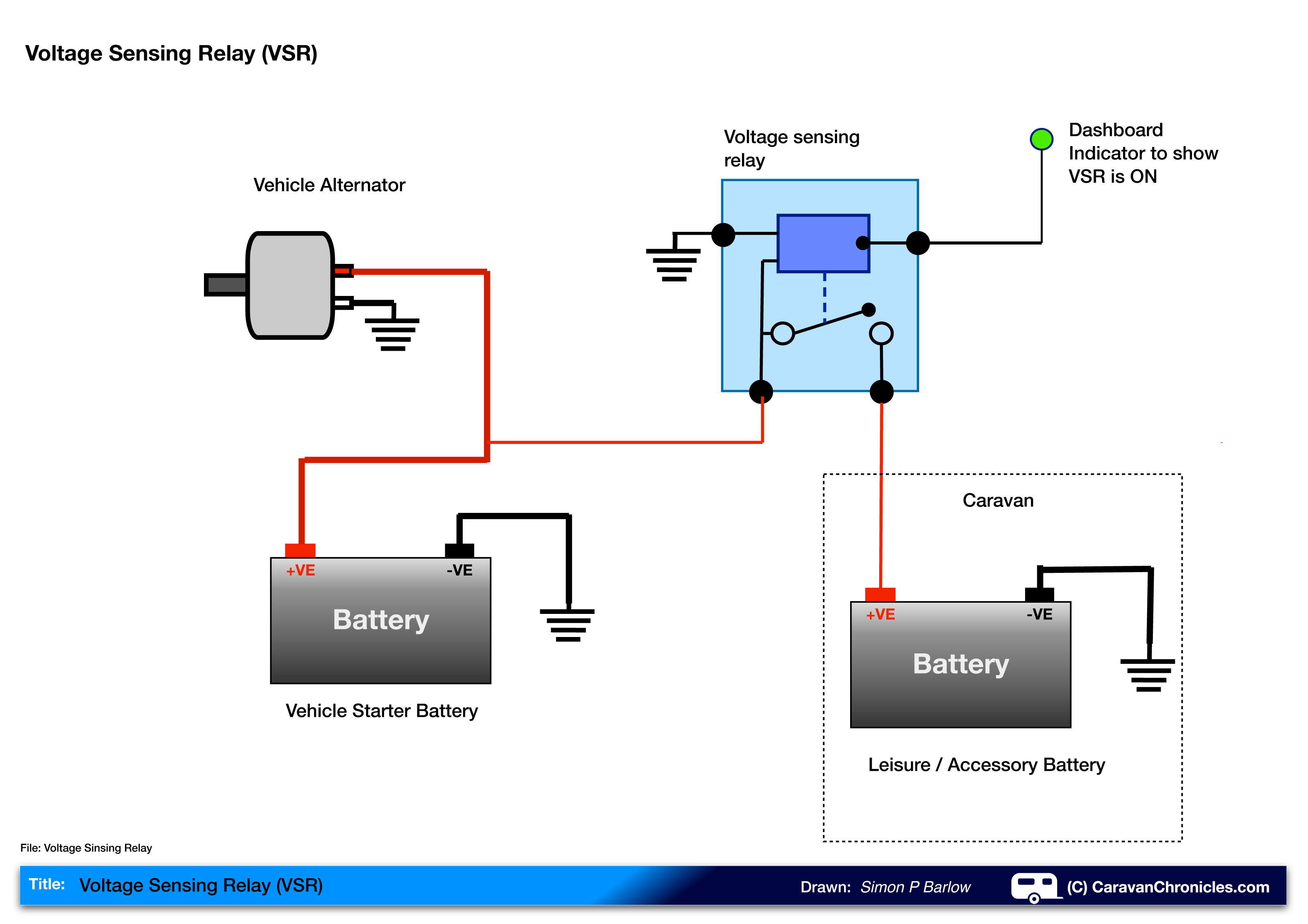
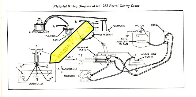
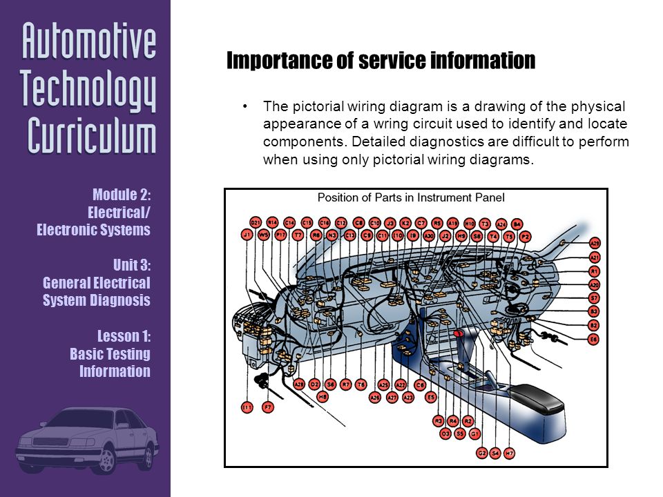
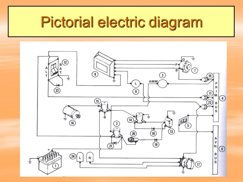
The least useful of the main electrical wiring diagrams is the pictorial diagram and for this reason alone its not commonly used. Figure 10 provides an example of the relationship between a schematic diagram figure 10a and a wiring diagram figure 10b for an air drying unit.

Circuit Diagram Wikipedia
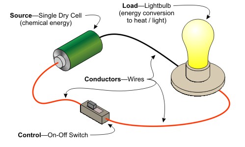
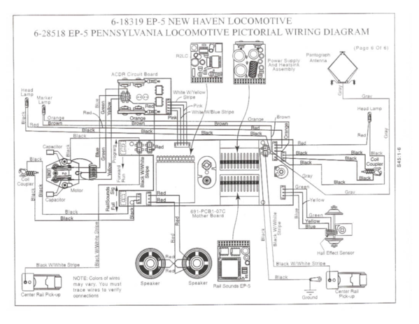
Pictorial electrical diagram. It shows a picture or sketch of the various components of a specific system and the wiring between these components. A wiring diagram is a simple visual representation of the physical connections and physical layout of an electrical system or circuit. They are mostly used for wiring installation in home and industries. This simplified diagram provides the means to readily identify the components of a system even if you are not familiar with their physical appearance. It shows how the electrical wires are interconnected and can also show where fixtures and components may be connected to the system. Unlike a pictorial diagram a wiring diagram uses abstract or simplified.
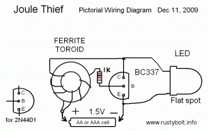
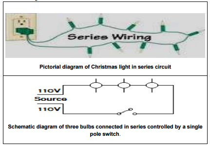
A more complex example the electrical circuit of an automobile is shown in wiring diagram format in figure 11 and in. Schematic circuit diagram a schematic. Symbols that represent the components in the circuit and lines that represent the connections between them. Figure 4 comparison of an electronic schematic diagram and its pictorial layout diagram. Pictorial diagram the simplest of all diagrams is the pictorial diagram. Wiring diagrams are made up of two things.
Figure aii 1pictorial diagram of a pump assembly. Wiring diagram shows a pictorial view of the components such that it resembles its electrical connection arrangement and position in real circuit. A wiring diagram is a type of schematic that uses abstract pictorial symbols to show all the interconnections of components in a system. It really helps in showing the interconnections in different equipment such as electrical panel and distribution boxes etc. Isometric diagram the purpose of an isometric diagram is to help you locate a component within a system. Reading electronic prints diagrams and schematics.
Figure 9 comparison of an electrical schematic and a pictorial diagram. To properly read prints and schematics the reader must identify the condition of the components shown and also follow the events that occur as the circuit functions. By connecting realistic electrical components with the wiring a pictorial diagram makes it easy and quick for viewers to identify the electrical components of a system immediately without professional knowledge required. Pictorial diagrams are much easier to understand than schematic circuit diagrams. After studying the pictorial diagram you should recognize the components and how they are connected to one another. It makes no attempt to be an accurate representation of the circuit but concentrates on the components in the circuit.
