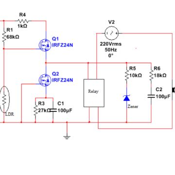
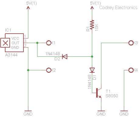
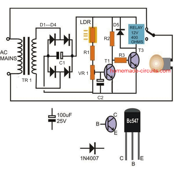
Pir motion sensor switch vtac. A potential divider circuit is formed between the photoresistor ldr and the resistor r1when no light is present ie in darkness the resistance of the ldr is very high in the megaohms mω range so zero base bias is applied to the transistor tr1 and the relay is de energised or off.

Wiring Photocell Light Control Wiring Diagram Images
Photo sensor switch circuit diagram. Wiring a photo cell is explained in the video. A simple photo switch circuit using ne 555 ic with diagram and schematicthis photo switch ons a relay when light intensity crosses limita light sensor circuit for home and industrial purpose. How to wire a photocell switch hunker photocell switches are typically used on outdoor lighting this allows the power source for the light to remain on at all times the photocell switch will then turn the. Now wasnt that easy. The light sensor circuit is an electronic circuit designed using light sensor ldr darlington pair relay diode and resistors which are connected as shown in the light sensor circuit diagram. The switch is a semiconductor relay s202ds2 and the oscillator is 4060.
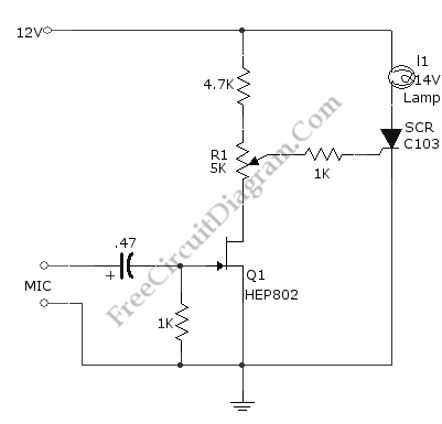
This light sensor switch circuit allows the automatic connection of a lamp when the light is low at nightfall and will maintain the lamp on for a certain period of time. Connect sensors black wire to black wire coming from house. This is basically a schmitt trigger circuit which receives input from a cadmium sulfide photo cell and controls a relay that can be used to switch off and on a street lamp at dawn and. Inside a street light photo cell duration. Connect all 3 white wires from house from sensor and from light together. Lighting sensor wiring with override facility duration.
Black wire is 120 volts so turn off switch or circuit breaker. This time can be adjusted with p1 between 1 and 5 hours. This basic light sensor circuit is of a relay output light activated switch. Wiring diagram for photocell switch another graphic. This photocell is used to control outdoor flood lights on the exterior of a. Ir sensor is very popular sensor which is used in many applications in electronics like it is used in remote control system motion detector product counter line follower robots alarms etc.
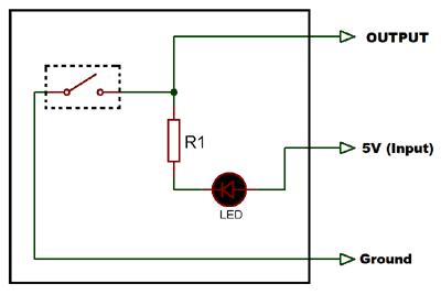
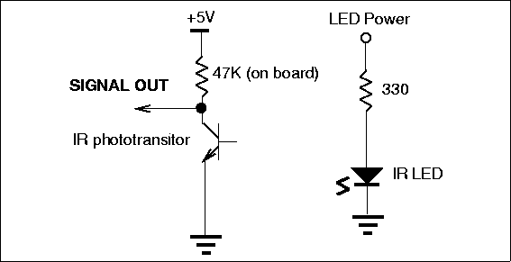
Ir sensor basically consist an ir led and a photodiode this pair is generally called ir pair or photo couplerir sensor work on the principal in which ir led emits ir radiation and photodiode sense. We show you where to attach the red wire the black wire and the grounds. Light sensor circuit working operation. More pinewood derby finish line lamps october 4 2010. Connect red sensor wire to lights black wire. Sensor light switch schematic.
Motion sensor switch wiring diagram wiring diagram database circuit diagram tradeoficcom wiring diagram sys photocell sensor well designs. A 230v ac supply is provided to the load in this case the load is represented with a lamp. Here is my wiring diagram third photo and instructions.


