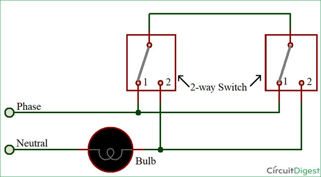
Here you can see there is a cut in the line wire connected to lamp 3 so the bulb is switch off and the rest circuit is working. There are two basic ways in which to connect more than two circuit components.
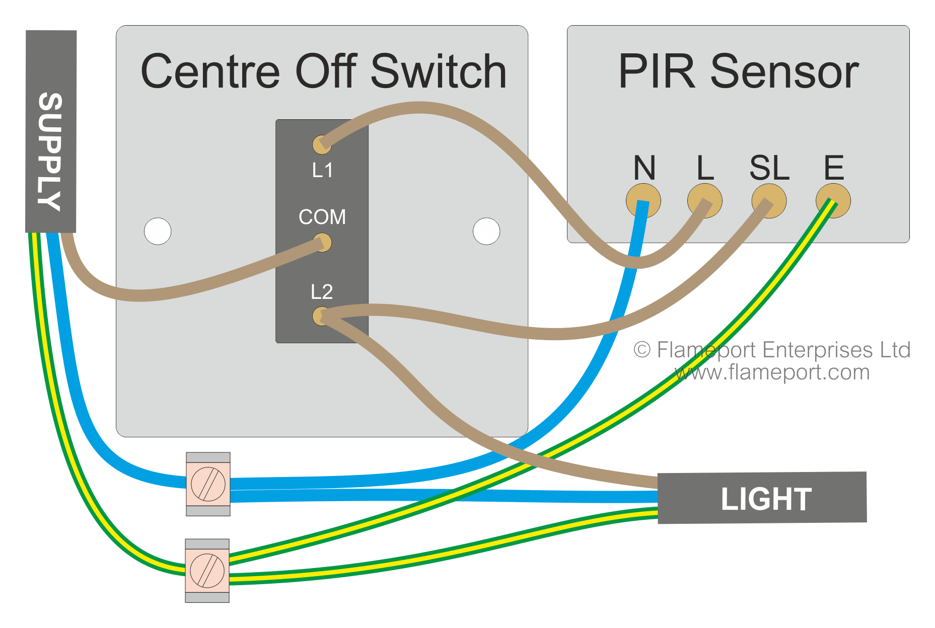
Motion Sensor Wiring With Switched Override Feature
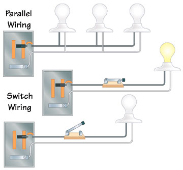
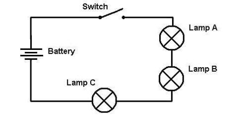
Parallel lighting circuit diagram. Here we have three resistors labeled r 1 r 2 and r 3 connected in a long chain from one terminal of the battery to the other. There are two parallel rails l and n. The common domestic circuits used in electrical wiring installations are and should be parallel. First an example of a series circuit. Here three lamps are connected to the supply. How to combine lights points in parallel.
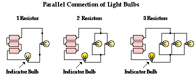
The wiring of lights in parallel connection is too simple and easy you need to connect to supply to each light bulb from the power source or we can said that the electric supply will connect to lights in parallel as i shown the below diagram. And from the parallel circuit rule number 3 we know that total current output gets divided by the number of parallel strings. The electrical system consists of the line from the pole a meter where electrical usage is tallied a main circuit breaker panel sometimes called load centers and in older homes fuse. Components connected in series are connected along a single conductive path so the same current flows through all of the components but voltage is dropped lost across each of the resistances. Circuit 3 of simple led circuits leds in parallel the final circuit in the simple led circuits tutorial is leds in parallel. All mains lighting circuits are wired in parallel.
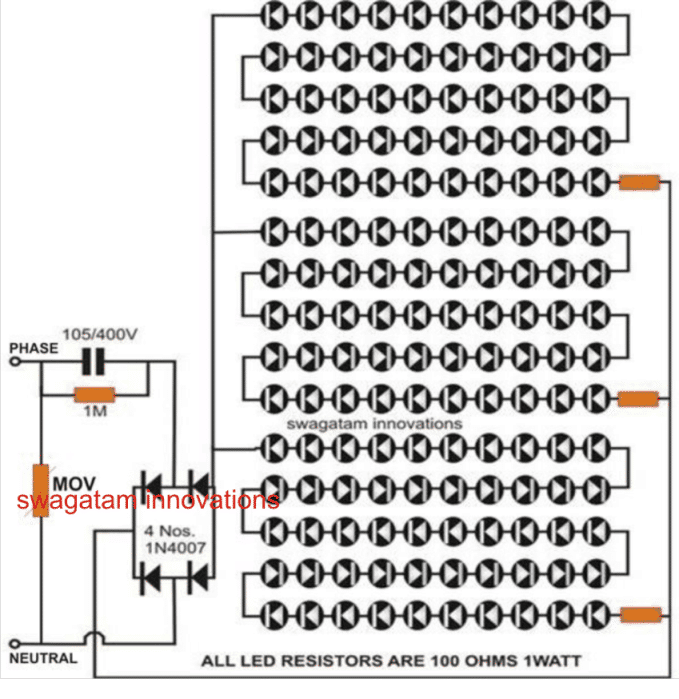
Also if we control each lamp by single way spstsingle pole single through switch in parallel lighting circuit we will be able to switch on off each bulb from from separate switch or if we switch off a bulb the rest lighting points wont affected as is it happens only in series lighting connection where all the connected load would be disconnected. Another major defect of series lighting circuit is that as all lamps or bulbs are connected between line l and neutral n accordingly if one of the light bulb gets faulty the rest of the circuit will not work as the circuit will be open as shown in fig below. The circuit diagram for leds in parallel connection is shown in the following image. Series wiring can occur when errors are made or when manufacturers of decorative lighting sets use cheap designs. Components of an electrical circuit or electronic circuit can be connected in series parallel or series parallel. Wiring lights in parallel connection diagram.
Series and parallel circuits. Faults in parallel lighting circuits. Each lamp is connected between l and n. Often switches outlets receptacles and light points etc are connected in parallel if one of them fails to maintain the power supply to other electrical appliances and devices through hot and neutral wires. The two simplest of these are called series and parallel and occur frequently. It should be.
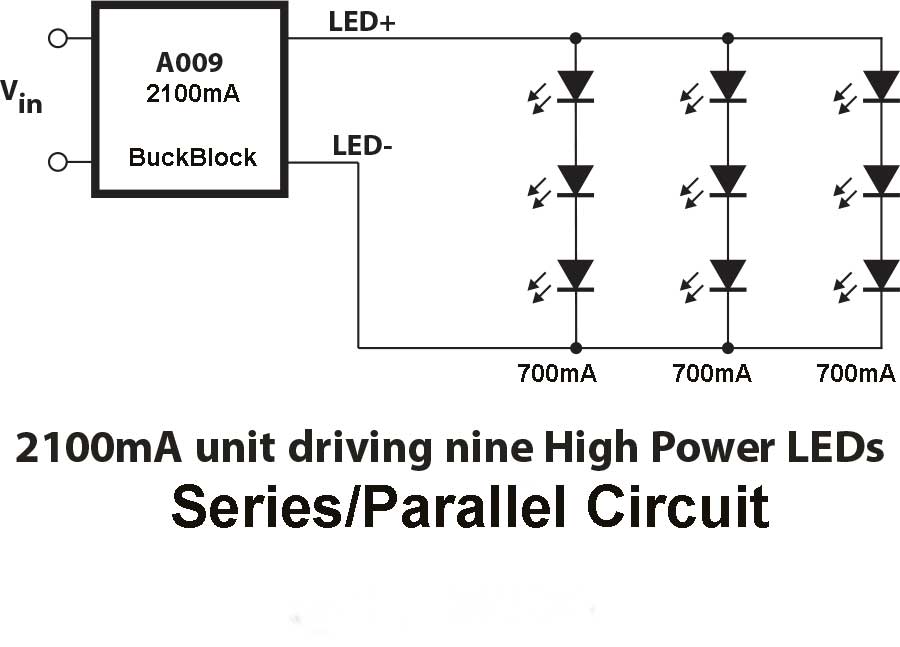
So if we were to use a 2100ma buckblock and have three parallel strings of 3 leds in series then the 2100ma would get divided by three and each series would receive 700ma. In this circuit we will try to connect three 5mm white leds in parallel and light them up using a 12v supply.

