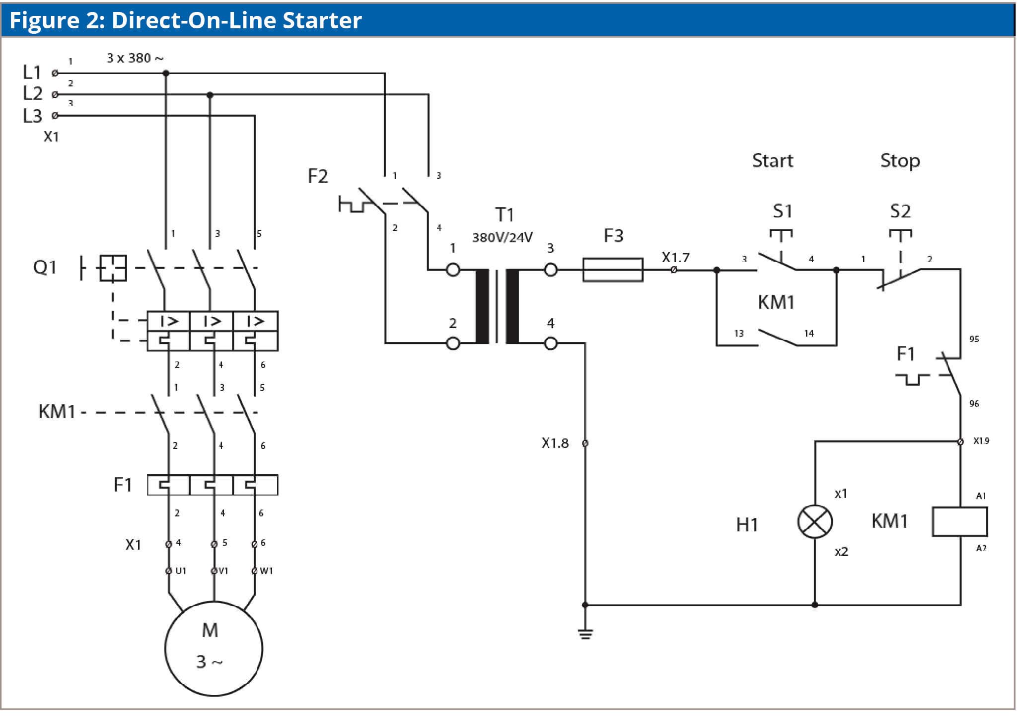
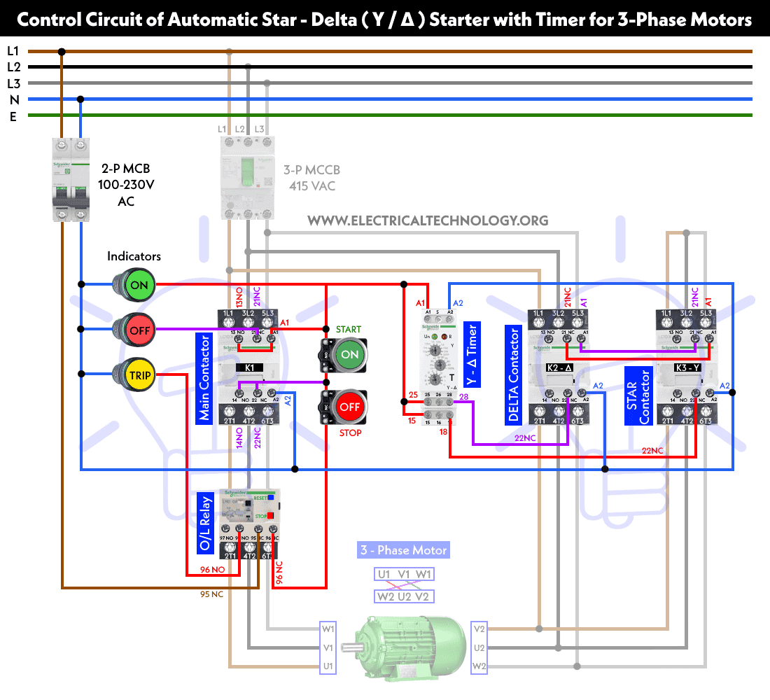
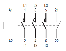
A wiring diagram is a simplified traditional photographic depiction of an electric circuit. Comparison of nema and iec schematic diagrams general.

Square D 8903 Lighting Contactor Wiring Diagram Lighting
Nema motor starter wiring diagram. Square d motor starters wiring diagram sq d motor starter wiring diagram square d 3 phase motor starter wiring diagram square d 8536 motor starter wiring diagram every electric structure is composed of various distinct pieces. Collection of nema size 1 starter wiring diagram. If you have a 120v coil instead of running a line from coil overload l2 you must run coil overload neutral. A motor starter is a combination of devices used to start run and stop an ac induction motor based on commands from an operator or a controller. Each part should be placed and linked to different parts in specific way. It reveals the parts of the circuit as simplified forms and also the power and signal links in between the devices.
Available nema size 00 7 for non reversing and nema size 00 5 for reversing electric motor applications. Machine tool or a simple across the line motor starter the need to recognize and understand these. 3ph starter3ph motor line voltage control three phase 3ph motor starter controlling a three phase motor rev 08 aug 2006 the above wiring diagram assumes your magnetic starter has a 240v coil. In north america an induction motor will typically operate at 230v or 460v 3 phase 60 hz and has a control voltage of 115 vac or 24 vdc. Class 8536 and class 8736 type s magnetic starters are used to switch ac inductive motors with a variety of overload relay options. The purpose of this document is to provide a simple cross reference of common schematicwiring diagram symbols used throughout various parts of the world.
Type s nema motor starters are designed for operation at 600 vac max up to 600hp and with a max of 810a. If not the structure wont work as it ought to be.


