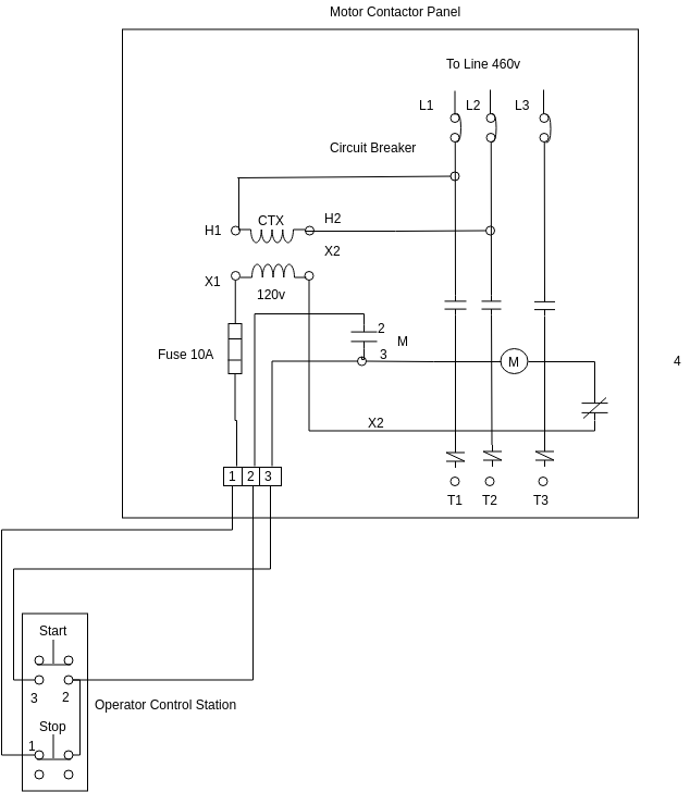
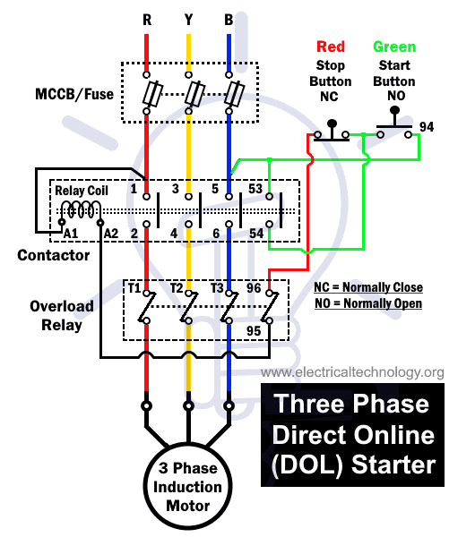
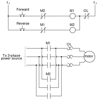
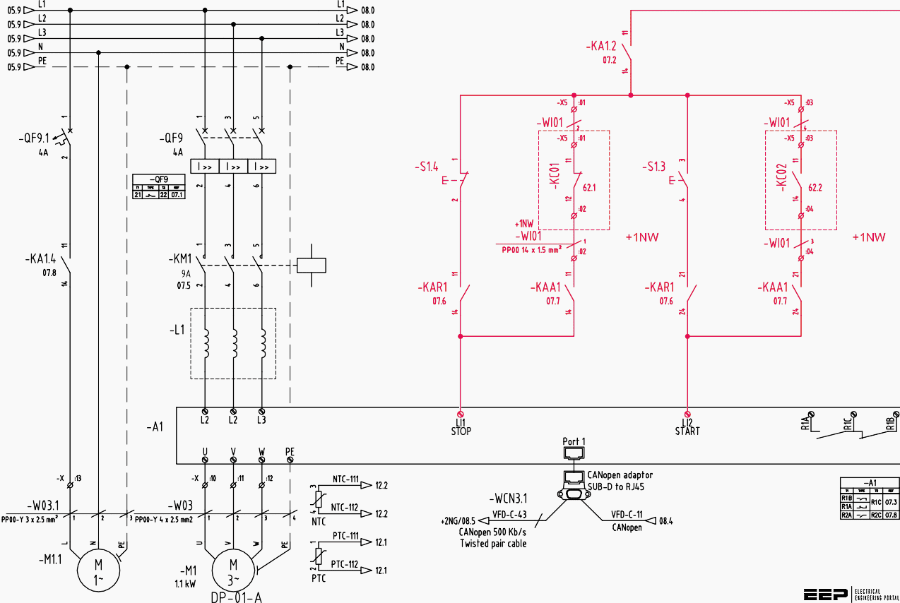
Feb 5 2020 explore elects agass board electrical diagram on pinterest. Basic wiring for motor contol circuitry of a starter the two circuits of a motor starter are the power and con trol circuits.

Aim Manual Page 56 Single Phase Motors And Controls
Motor wiring circuit. In todays video i do a complete how to walk through on properly installing the electrical components on a 24 volt trolling motor setup with 6awg wiring and a 60 amp circuit breaker from minn kota. Motor start capacitors are used during the motor startup phase and are disconnected from the circuit once the rotor reaches a predetermined speed which is usually about 75 of the maximum speed for that motor type. Three phase motor power control wiring diagrams 3 phase motor power control wiring diagrams three phase motor connection schematic power and control. Also read about the speed torque characteristics of these motors along with its different types. Check the motor manufacturers manual for recommendations on the correct wiring hookup for your application. Motor start and motor run capacitors start capacitors.
Variety of 240v motor wiring diagram single phase. Tips to attract fine looking electrical wiring diagrams. There are two circuits to a starter the power circuit and the control circuit. Click here to view a capacitor start motor circuit diagram for starting a single phase motor. Please provide the auto changeover scheme circuit between two dol feeders whether i can also manually start any of two dol feeders by selector switch. See more ideas about electrical diagram electrical circuit diagram electrical engineering.
If there is not a manual with the motor look for a hook up schematic somewhere on the motor. Waiting for your valuable reply. Learn how a capacitor start induction run motor is capable of producing twice as much torque of a split phase motor. A series circuit is a circuit in which parts are attached along a solitary course so the current flows through one component to get to the next one. A wiring diagram is a streamlined conventional pictorial depiction of an electric circuit. In a collection circuit voltages add up for all elements attached in the circuit and currents are the same with all parts.
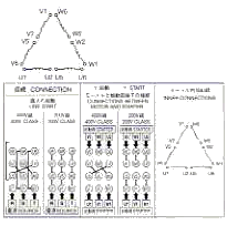
The schematic may be on the exterior of the motor or possibly under an inspection plate or cover of the motor. The electricity that passes through the contacts of the starter through the overload relay and out to the motor is called the power. Wondering how a capacitor can be used to start a single phase motor. It reveals the components of the circuit as simplified shapes as well as the power and also signal connections in between the tools.
