How a car starting system works. On the manual mode motor a and motor b can be controlled separately by selector switch.
Resolved Electrical Problem Slide Out Will Not
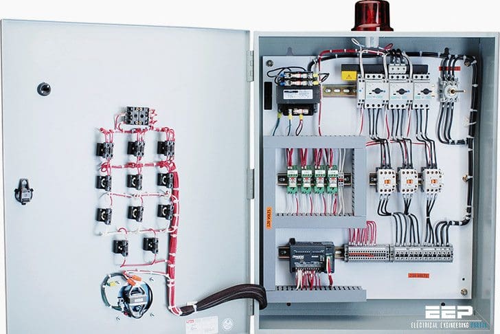
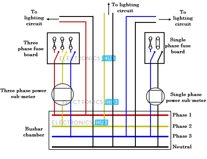
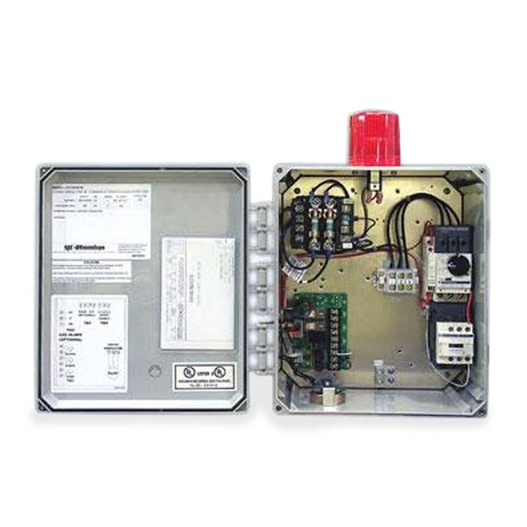
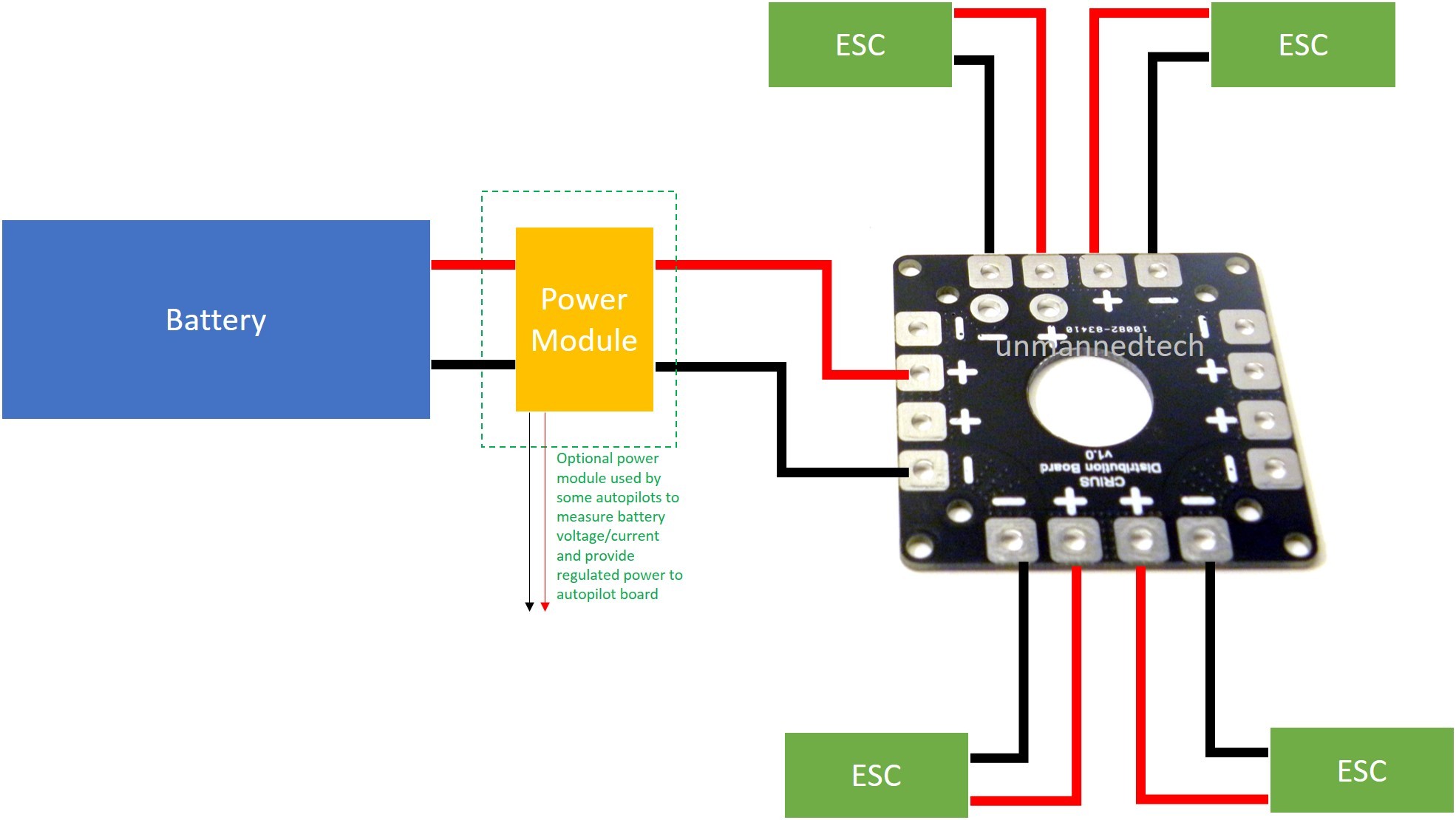
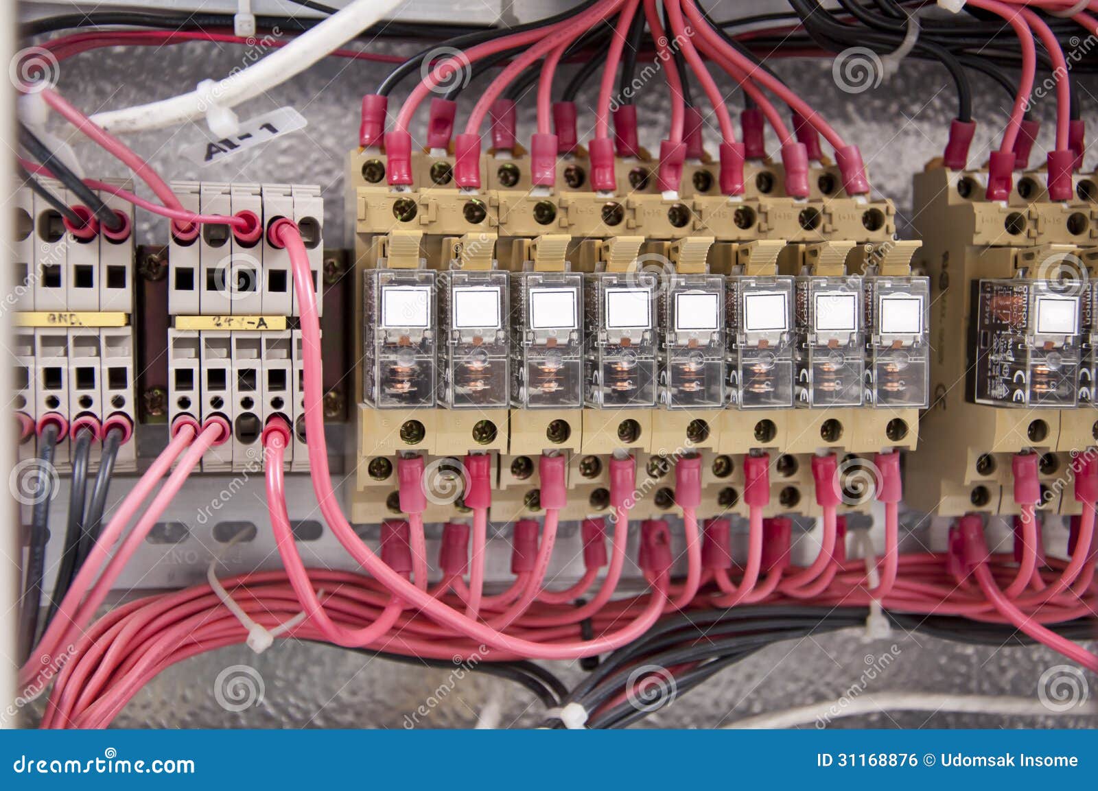
Motor panel board wiring diagram. Fine how to install electrical panel board inspiration best. A 3 phase panel board wiring diagram or 3 phase distribution board wiring diagram. Electric motor drawing at getdrawings. In which mccb circuit breakers volt meters ampere meter with current transformer light indicator earthing connection and bus bar with complete wiring diagram. Can you help me with the controlled diagram. Dashed lines indicate a single purchased component.
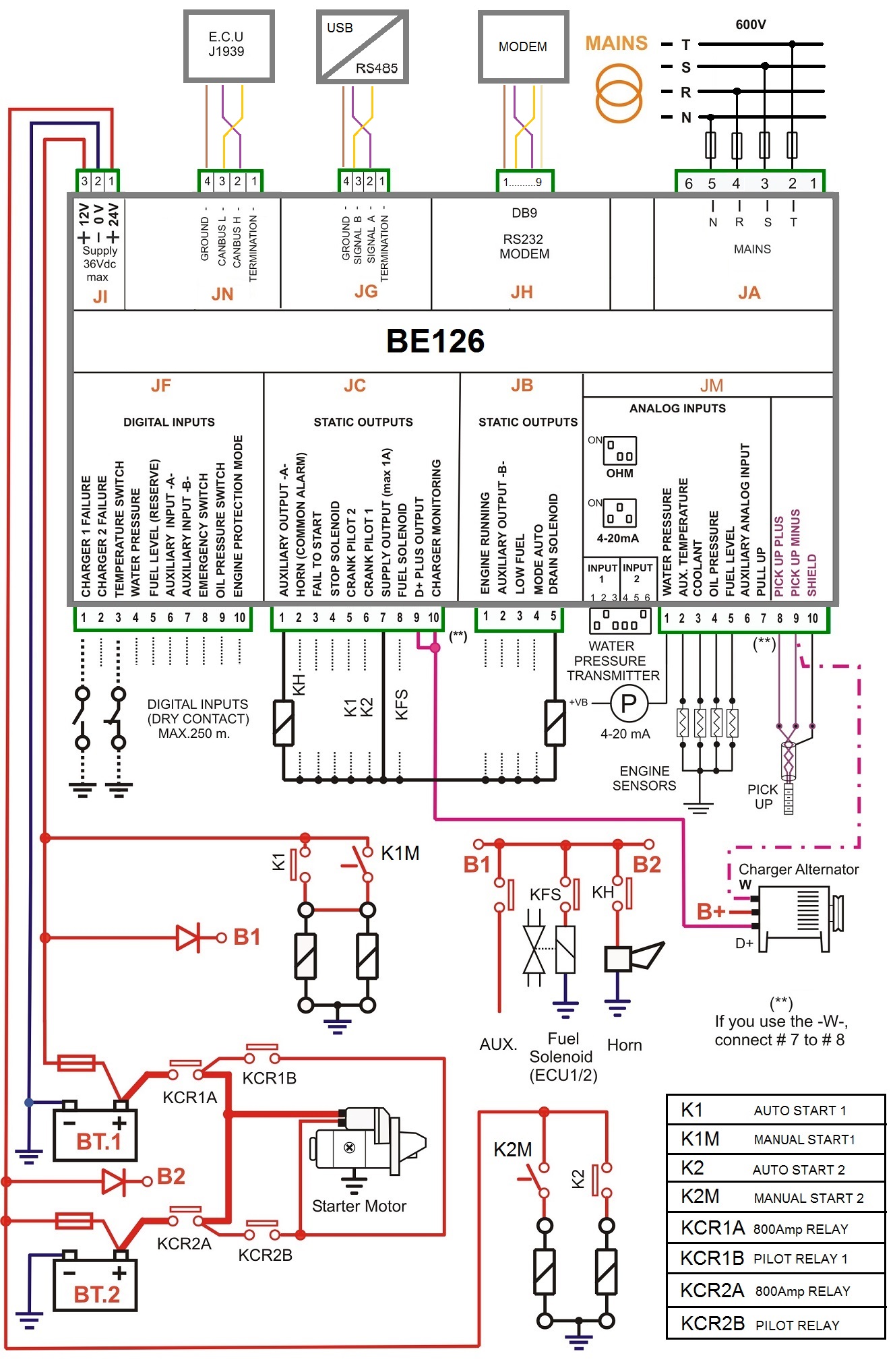
On the automatic mode motor a has to run for 3 minute then motor b comes on also. Motor control panel wiring diagram pdf wiring diagram is a simplified within acceptable limits pictorial representation of an electrical circuitit shows the components of the circuit as simplified shapes and the aptitude and signal associates in the middle of the devices. System diagram starter motor solenoid starter relay neutral safety switch. The three phases are then connected to a power interrupter. This system uses 3 phase ac power l1 l2 and l3 connected to the terminals. Sel generator control panel wiring diagram genset controller.
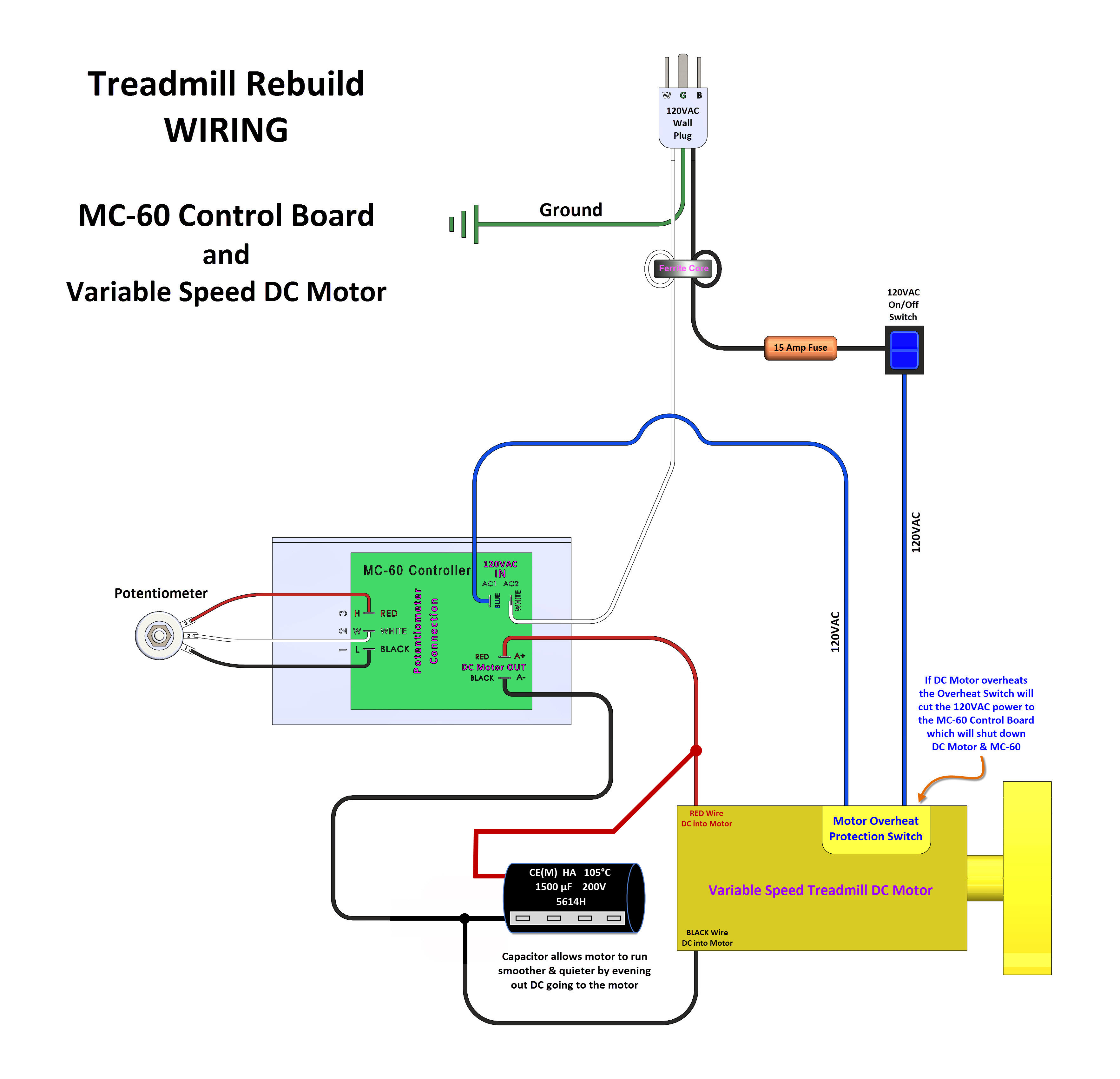
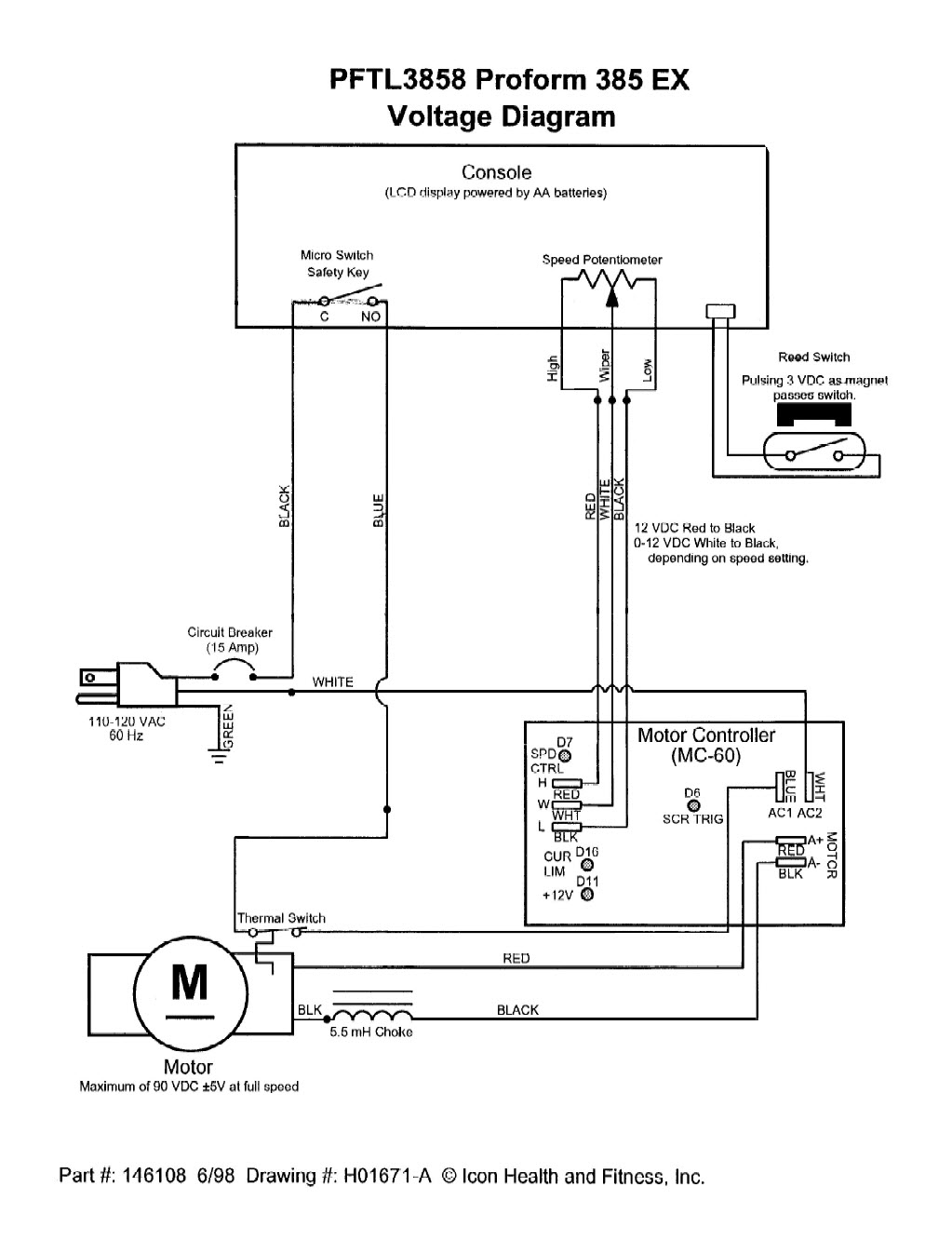
Note that symbols are discussed in detail later. An example of a wiring diagram for a motor controller is shown in figure 1. Electrical control panel wiring diagram pdf download diesel generator control panel wiring diagram. Common starting system problems testing.
