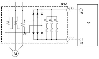
Three phase motor connection schematic power and control wiring installation diagrams. Star delta y δ 3 phase motor starting method by automatic star delta starter with timer.

Four Point Manual Dc Motor Starter Circuit Diagram
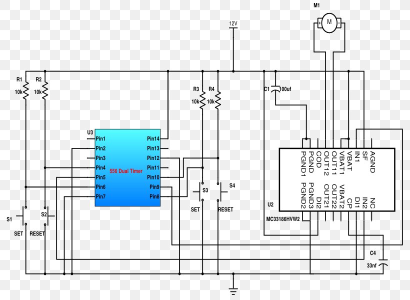
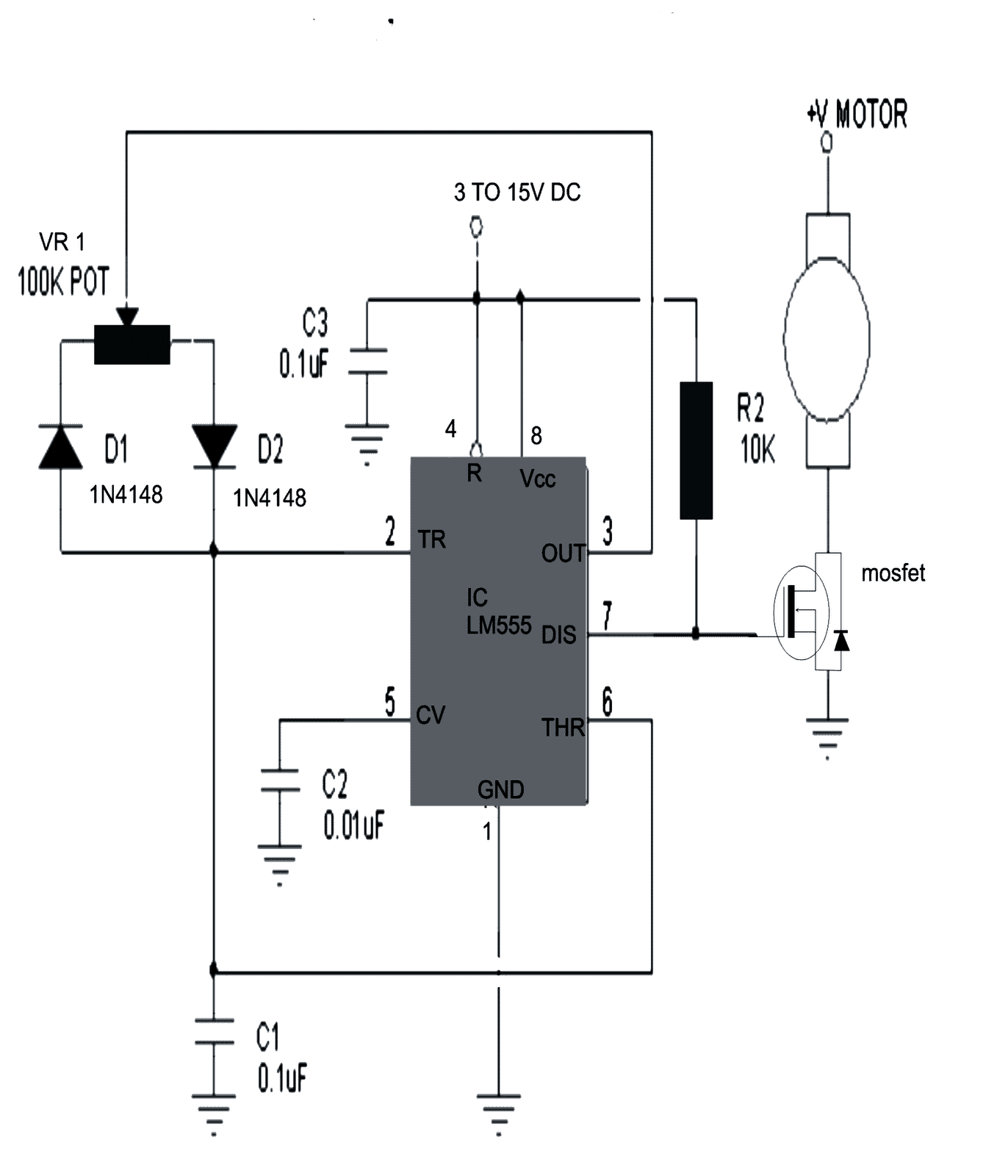
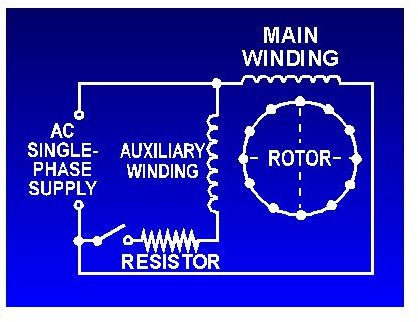
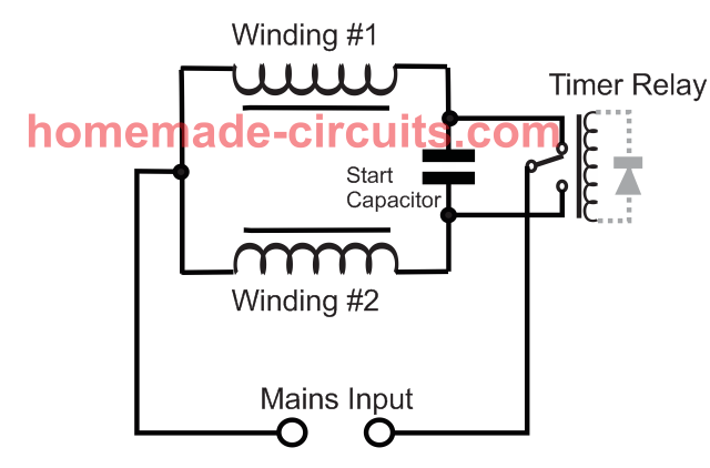
Motor in circuit diagram. Single phase electric motor wiring diagrams. Variety of 240v motor wiring diagram single phase. Motor contactor or starter coils are typically designated by the letter m in ladder logic diagrams. The interlock contacts installed in the previous sections motor control circuit work fine as discussed in previous article but the motor will run only as long as each pushbutton switch is held down. Interpret this ac motor control circuit diagram explaining the meaning of each symbol. A wiring diagram is a streamlined conventional pictorial depiction of an electric circuit.
Allen allen rio negro asociacion volantes mar y valle trelew chubut auto club pigüé pigüé buenos aires auto club salta aka. Andorra ice racing circuits. Design circuits online in your browser or using the desktop application. Where can i find single phase electric motor wiring diagrams. Barrio autódromo salta autódromo 9 de julio 9 de julio buenos aires autódromo aldea romana de bahía blanca bahía blanca buenos aires. It reveals the components of the circuit as simplified shapes as well as the power and also signal connections in between the tools.
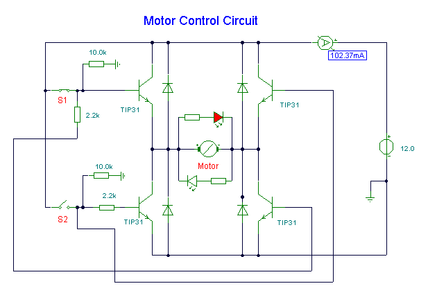
Also explain the operation of this motor control circuit. Pas de la casa pic maiá andorra la vella argentina permanent circuits. Types of dc motor a direct current motor dc is named according to the connection of the field winding with the armaturemainly there are two types of dc motors. Already we discussed about the basics of permissive and interlock circuits in previous post also discussed about the basic motor control logic using forward reverse control. A wiring diagram is a simplified standard pictorial representation of an electrical circuit. First one is separately excited dc motor and self excited dc motor.
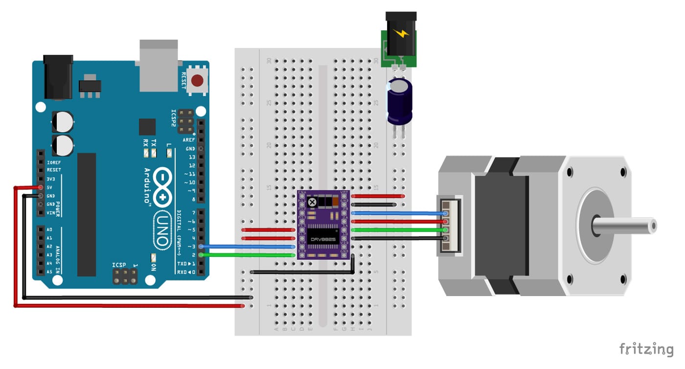
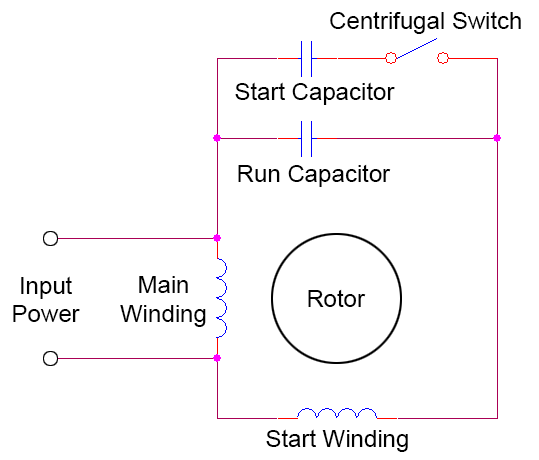
Single phase motor internal wiring diagrams. Assortment of stepper motor wiring diagram. It shows the components of the circuit as simplified forms as well as the power and also signal links in between the tools. Continuous motor operation with a momentary start switch is possible if a normally open seal in contact from the contactor is connected in parallel with the start switch so that once the contactor is energized it maintains power to itself and keeps itself latched on. Three phase motor connection stardelta without timer power control diagrams. Circuit diagram is a free application for making electronic circuit diagrams and exporting them as images.
Based on your observations of these two diagrams explain how electromechanical relays are represented differently between ladder and schematic diagrams. At the bottom of this post is also a video about dc shunt motors. I have compiled a list of single phase electric motors and their wiring diagrams below. The self excited motors are further classified as shunt wound or shunt motor series wound or series motor and compound wound or compound motor.

